FORM-ENG-0018 REV A 05-27-03
607 NW 27th Ave
Ocala, FL 34475
Ph: 352-629-5020 or 1-800-533-3569
Fax : 352-629-2902 or 1-800-520-3473
S U I T A B L E F O R E X T E R N A L D I S T R I B U T I O N
OPERATION MANUAL
MANUAL P/N:118253 PRINTED: 6/12/19
No passwords are
accepted.
If the display flashes “X” four times after entering a password, insure the display is
installed right side up. During power-up the display should turn on all LEDs and
then cycle them OFF starting with the top row, then the display should scroll the
custom greeting from right to left.
Check that the left and right magnetic switches are recognized by activating each
switch and verifying that the associated LEDs illuminate.
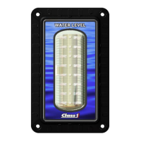
The bottom four LED
rows are on and
occasionally they go out
and the top four LED
rows flash and then
return to the bottom four
LED rows on (or vice-
versa). (REMOTE).
Check for large noise spikes on the 1-wire data line.
Insure that the display’s ground potential is the same as the MASTER’s.
Insure that the data line is not chaffed and making contact with other electrical
wires.
The points calibrated
seemed to have
changed.
Check the pressure sensor for problems.
Recalibrate the display and take a voltage reading from the sensor (pin 6 on the
display’s connector) at each calibration point. When the calibration points again
look wrong check the voltages at those points and determine if they are the same
as the voltage reading taken during calibration – if they are not then replace the
sensor.
Unit will not dim display.
Insure the Dim input voltage on Pin 4 is at least 9V. Recalibrate dim setting
(RLLR LLLR). If display does not dim LEDs while in the dim configure mode,
replace display.
The middle two LED
rows are flashing
together.
A calibration was started on the display but not completed correctly. Set the
display to a REMOTE display (LRLR LRLR) or calibrate it as a MASTER (follow
calibration steps exactly).
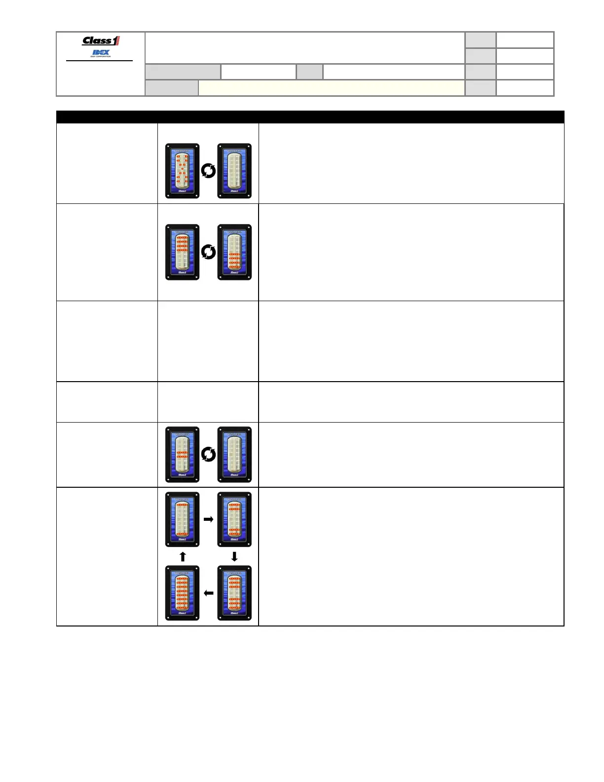
LEDs cycle ON toward
the center continuously.
The display has had a unit type memory error.
Attempt to set the display back to REMOTE or MASTER as required.
Replace the display if this error cannot be corrected.
7.2. Using the display to verify pressure sensor signal voltage
The display can show the voltage level that it detects on the pressure sensor signal line by entering the password
LLRR LLRR.
The display will then scroll the text “VOLTS” and then continue to scroll the voltage detected at pin 6.
The display will continue showing the voltage until either of the magnetic switches is activated.