iDirect Evolution X5 Satellite Router Installation and Safety Manual 29
Preparing the Coax Cables
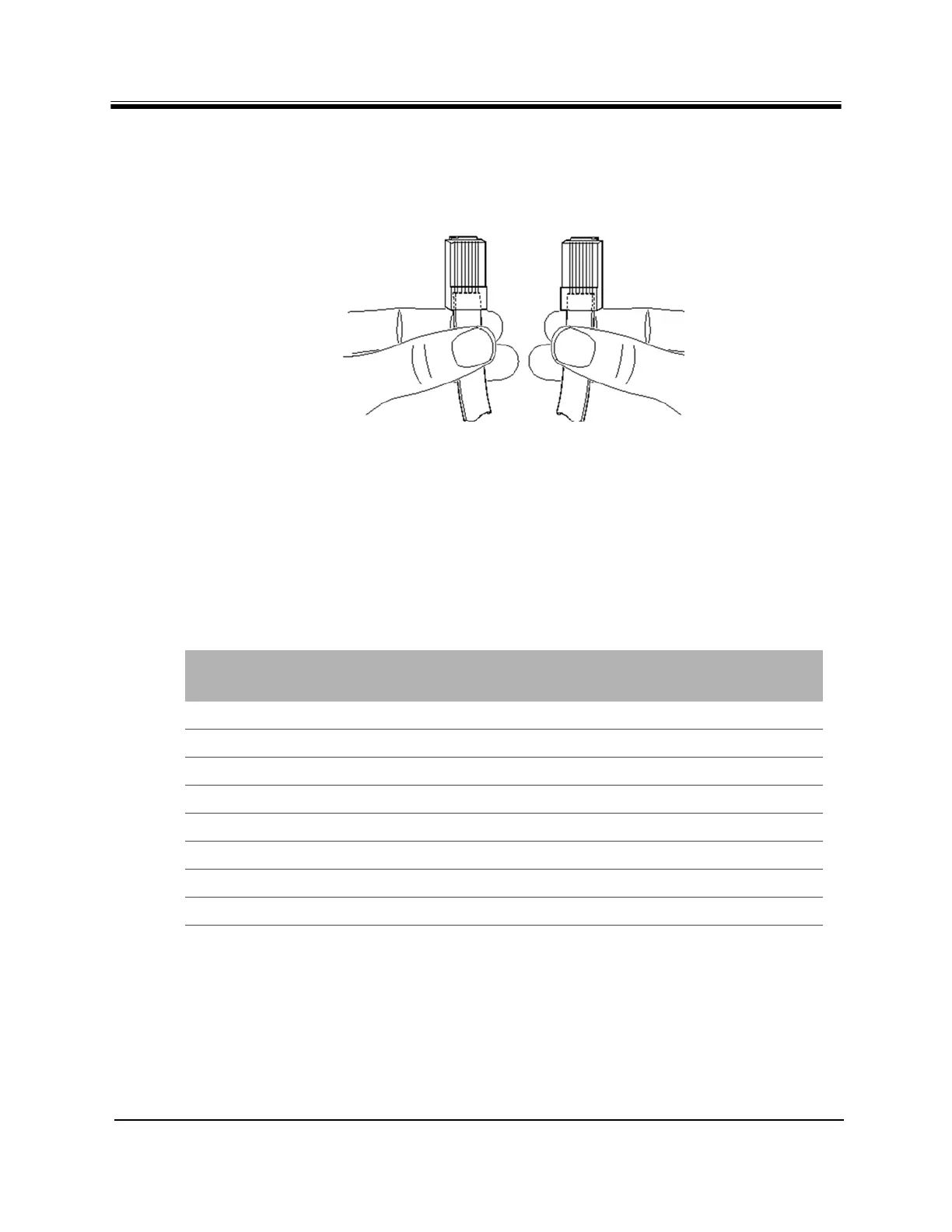
Holding the RJ-45 cable connectors side by side with the tab at the back, as shown below,
examine the sequence of the colored wires to determine the type of RJ-45 cable as shown in
Figure 14.
Figure 14. Holding the RJ-45 Cable Connectors
• Straight through — The colored wires are in the same sequence at both ends of the cable.
• Crossover — The first (far left) colored wire at one end of the cable is the third colored
wire at the other end of the cable.
Table 11 lists the signal and pinouts for the asynchronous serial Console Port and the RJ-45 to
DB-9 female DTE adapter. A picture of the adapter is shown Figure 15 on page 30.
Table 11. RJ-45 to DB-9 Pinouts
Console Port
(DTE)
RJ-45 Pin Color Code
RJ-45 to DB-9
Terminal Adapter
Console
Device
RTS 1 Blue 8 CTS
DTR 2 Orange 6 DSR
TxD 3 Black 2 RxD
GND 4 Red NC GND
GND 5 Green 5 GND
RxD 6 Yellow 3 TxD
DSR 7 Brown 4 DTR
Rx-RF-Power 8 White/Grey 9 --