8 IDS1600 USER MANUAL NO. 700-146-01D ISSUED NOV 2002 VER 2.17
IDS1600 USER MANUAL
2.1 Notes on the LCD Keypad
Refer to illustration on inside back cover of the manual.
0 1 / 0 1 / 9 9 0 : 0 4
R E A D Y MO N
MRA ELBUORT
The illustration above shows what text is shown on the LCD
display as well as the status of the ARM and TROUBLE
indicators. Below is a key showing the three possible states of
the indicators and the symbols used to represent them.
detanimull
Where procedures followed for programming functions are the
same for the two keypads, illustrations showing the LCD display
and indicator status will accompany the text directions for the
LED keypad.
Where procedures vary between the keypads, the directions and
illustrations for the LCD keypad procedure will follow those of the
LED keypad. For easy distinction of instructions, the instructions
for the LCD keypad are shaded in grey.
NOTE:
There is a section at the end of the manual dedicated to explaining the
navigation of the LCD keypad menu.
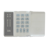
3. Operation of the LED Keypad
To ensure correct operation of your security system it is essential to
familiarize yourself with the use of the keypad.
The keypad has a buzzer, command entry keys and zone and
system status L.E.D.’s.
The keypad is used to send commands to the system and to
display the current system status.
The keypad(s) will be mounted in a convenient location within