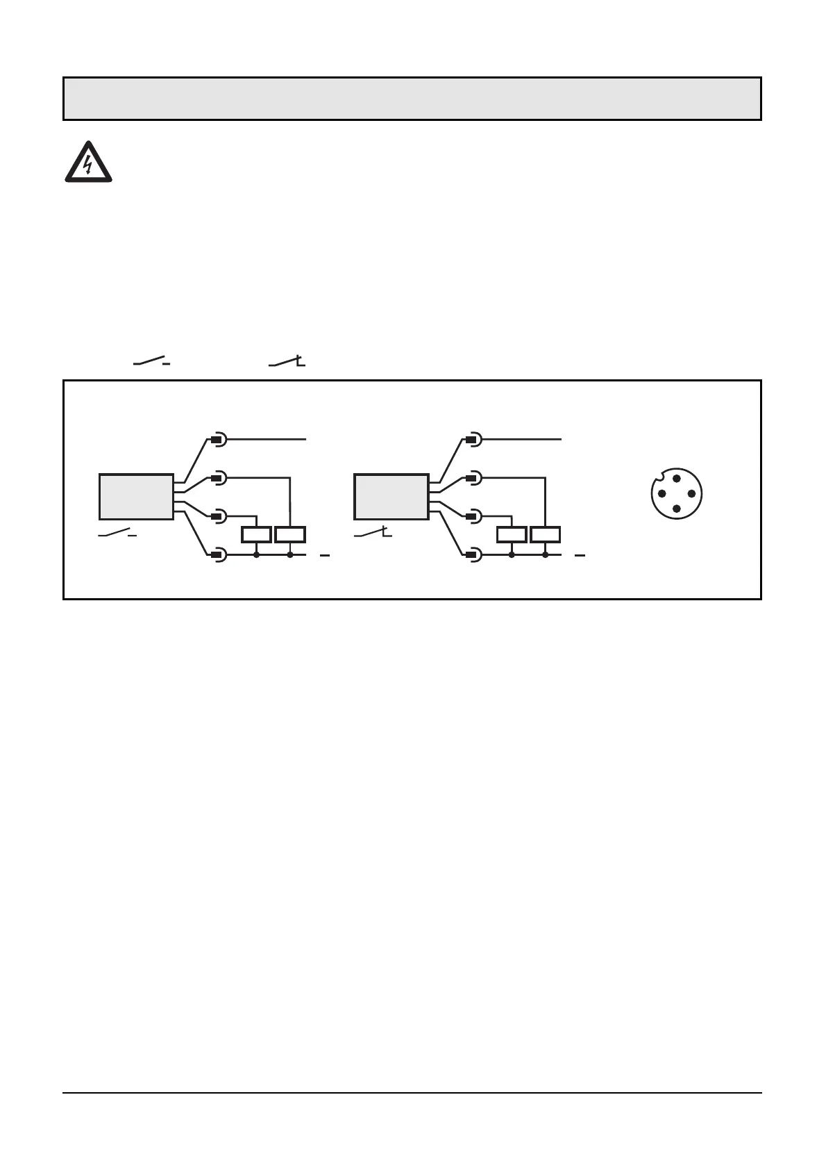
The unit must be connected by a suitably qualified electrician.
The national and international regulations for the installation of
electrical equipment must be observed.
Voltage supply to EN50178, SELV, PELV.
The device shall be supplied from an isolating source and
protected by an overcurrent device such that the limited voltage
circuit requirements in accordance with UL 508 are
met.Disconnect power before connecting the unit as follows
( = N.O. / = N.C.):
When the supply voltage is applied, all LEDs light and go off one after
the other.* The unit is then ready for operation.
*During this time the output is switched according to the programming: ON
with the N.O. function and OFF with the N.C. function.
Failure indication:
5 left LEDs flashing in case of short-circuit at the switching output S1;
5 right LEDs flashing in case of short-circuit at the switching output
S2.
26
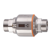
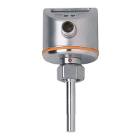
connector
view (sensor)
S1 = flow monitoring
S2 = temperature monitoring or logic combination flow / temperature
(logic function)
Core colours of ifm sockets:
1 = BN (brown), 2 = WH (white), 3 = BU (blue), 4 = BK (black)
Electrical connection