■■
Setting of the detection range
The detection range (window)
is determined by:
• Adjustment to the required
maximum flow (HI-Teach)
= upper limit of the window.
This setting is sufficient for the
majority of waterbased appli-
cations.
• Adjustment to the required
minimum flow / flow standstill
(LO-Teach) = lower limit of the
window.
• Adjustment to maximum flow (HI-Teach)
The unit detects the current flow and sets this value as the maximum
value for the LED display (LED 9).
30
Programming diagrams / Technical information
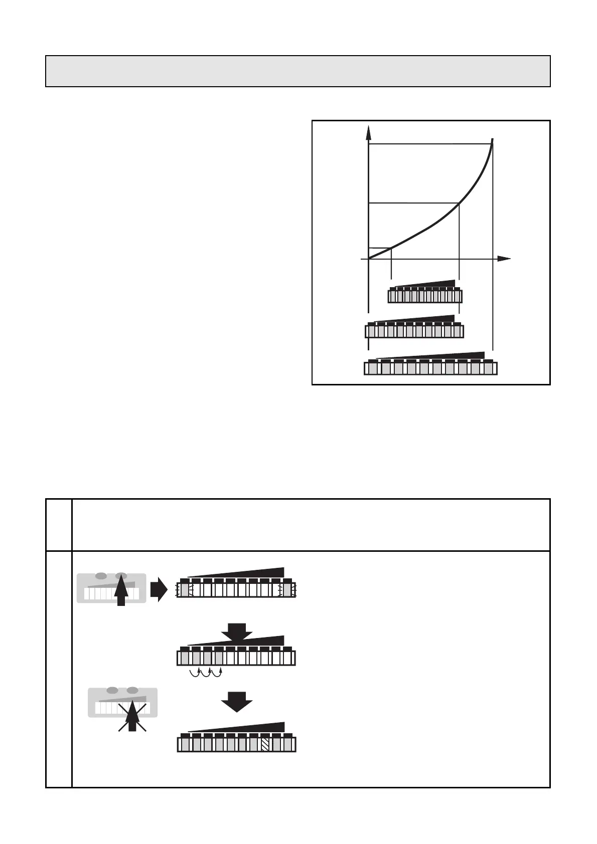
flow velocity
sensor
signal
1
2
Press the Learn/Set button and
keep it pressed.
The green LEDs on the right and
on the left flash,
after 5s the LED bar (green) fills
from left to right
(release the button as soon as the
first LEDs light).
The indication goes off briefly.
The unit stores the current flow as
maximum flow and passes into the
run mode flow.
Apply the operating voltage. After approx. 15s the unit is ready.
Ensure you are in run mode flow. Allow the medium to flow
through the system at the required maximum flow rate.