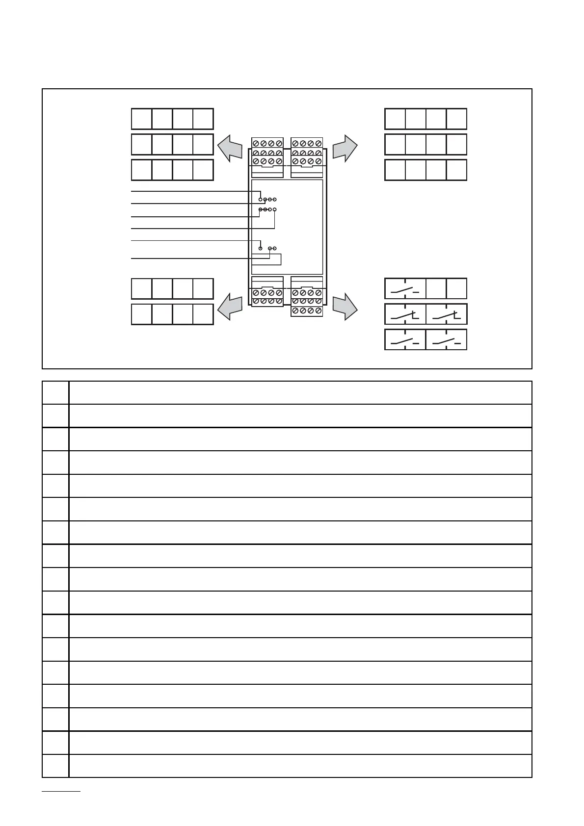
A1
Connection for the 3rd fail-safe switch/chain
A2
Connection for the 2nd fail-safe switch/chain
A3
Connection for the 1st fail-safe switch/chain
A4
Connection for the 4th fail-safe switch/chain
A5
Connection for the 5th fail-safe switch/chain
A6
Connection for the 6th fail-safe switch/chain
B1
LED yellow: clock output
B2
LED green: output clock of the connected fail-safe switches/chains (1..3)
B3
LED green: output clock of the connected fail-safe switches/chains (4..6)
B4
LED red: fault/start-up
B5
LED green: voltage supply
B6
LED green: triggering of the relay outputs
C1
Connection for voltage supply and programming
C2
Connection for external relay monitoring
C4
Connection relay output 1 x NO (closed for enabling)
C5
Connection relay output 2 x NC (open for enabling)
C6
Connection relay output 2 x NO (closed for enabling)