55
ifm Device Manual IO-Link Master with Modbus interface CabinetLine 8 Ports IP 20 (AL1940) 05 / 2018
Configuration Modbus
>
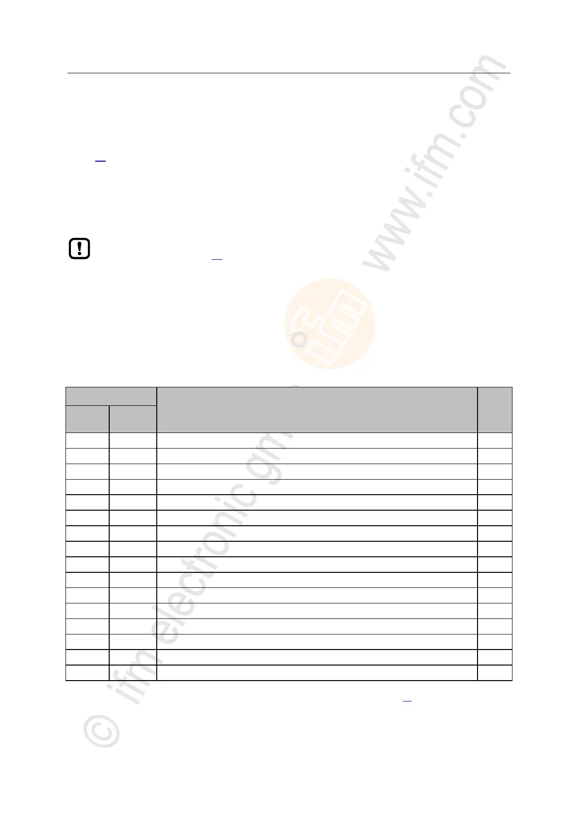
8.3.6 Write output data of individual IO-Link ports
23016
Register area for separate access to output data of individual IO-Link ports: → Single Port Access
(→ p. 82)
The area contains the following data for each IO-Link port X01...X08:
Digital output data at clamp 2
Digital output data at clamp 4 (DO)
IO-Link output data
► Observe the general rules for access to the Modbus registers (→ Rules for accessing the
Modbus register (→ p. 58))!
With one write command, several connected register areas of a IO-Link port can be written
(e. g. registers 1100 and 1101).
► When writing outputs, ensure that the length of the transferred output data corresponds
with the configured process data length.
The output data is invalid in the following situations:
no Ethernet cable connected
PLC has terminated the connection
Connection to the PLC has a timeout
Port X01: Digital Output - Pin 4 (DO)
Port X01: Output Data IO-Link (n bytes)
Port X02: Digital Output - Pin 4 (DO)
Port X02: Output Data IO-Link (n bytes)
Port X03: Digital Output - Pin 4 (DO)
Port X03: Output Data IO-Link (n bytes)
Port X04: Digital Output - Pin 4 (DO)
Port X04: Output Data IO-Link (n bytes)
Port X05: Digital Output - Pin 4 (DO)
Port X05: Output Data IO-Link (n bytes)
Port X06: Digital Output - Pin 4 (DO)
Port X06: Output Data IO-Link (n bytes)
Port X07: Digital Output - Pin 4 (DO)
Port X07: Output Data IO-Link (n bytes)
Port X08: Digital Output - Pin 4 (DO)
Port X08: Output Data IO-Link (n bytes)
r/w = read and write
n = [2,4,8,16,32]; is determined by parameters [Process Data Length] (→ Configuration Area (→ p. 73))
 Loading...