EasyManua.ls Logo

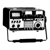
IFR FM/AM-1200A

IFR FM/AM-1200A
294 pages
To Next Page IconTo Next Page
To Previous Page IconTo Previous Page
Loading...
.
j
'
5-11
TRACKING
GENERATOR-
OPTION
12
(FM/
AM-12005
ONLY)
FM/AM-1200S
CONNECTORS
AND
INDICATORS APPLICABLE
TO
TRACKING
GENERATOR
OPERATION:
14
DUPLEX
Output
Connector
31
CRT
Display
34
ANT
Connector
37
VFD
Figure
5-4
FM/AM-1200S
Front
Panel
Controls
Applicable
to
Tracking
Generator
Operation
18
Keyboard
22 PWR/OFF/BATT
Switch
24 VERTICAL
ATTENUATOR
Selector
Control
25
HORIZONTAL
Sweep
Vernier
Control
26
HORIZONTAL
Sweep
Selector
Control
27
VERT
POS
Control
28
INT
Control
29
FOCUS
Control
30
HORIZ
POS
Control
39
MODE
Selector
Control
"As
req'd"
"Pl~R"
or
"BATT"
Any
position
except
"OFF"
Fully
cw
"1
MHz/Div"
"Mid
Range"
As
req'd
As
req'd
"Mid
Range"
DU
P
Table
5-4
FM/AM-1200S
Front
Panel
Controls
Applicable
to
Tracking
Generator
5-11-1
GENERAL
The
Tracking
Generator
option
allows
operators
to
accomplish
the
tuning
and
alignment
of
radio
communications
components
such
as
notch
dupl
exers,
circulators,
combiners,
isolators,
etc.
The
device
under
test
is
connected
between
the
swept
RF
output
present
at
the
DUPLEX
Output
Connector
(14)
and
the
input
to
the
Spectrum
Analyzer
at
the
ANTENNA
Connector(34).
5-15f
Blank/5-16

Table of Contents