EasyManua.ls Logo

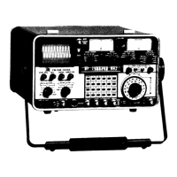
IFR FM/AM-1200A

IFR FM/AM-1200A
294 pages
To Next Page IconTo Next Page
To Previous Page IconTo Previous Page
Loading...
Table
4-6
(Cont'd)
SIGNAL
CHARACTERISTICS:
MONITORING
DEVICE(S):
CONTROL
SETTINGS:
#RF
ERROR
or
*AUDIO
ERROR
FREQ
ERROR
Meter
(36)
VFD
(37)
FREQ
ERROR
Meter
Range
Selector
Control
(35)
as
req'd.
Depress
"2ND
FUNCT"
and
"METER"
Keys
(in
that
order).
# Used
with
GEN/LOCK
Control
(32)
*Audio
error
is
measured
through
EXT
MOD/SINAD
Connector
(15).
Table
4-7
Receiver
Monitoring
Capabilities
of
Generated
Output
4-6-2
SIGNAL
GENERATOR
OPERATION
(SIMPLEX)
STEP
PROCEDURE
------------------------------------------------------------------------
1.
Position
front
panel
controls
as
indicated
in
Table
4-5.
FM/AM-1200S/A
is
now
generating
a
carrier
signal
at
a
frequency
and
output
level
of
150.2
MHz
@
500
].lV.
If
a
signal
greater
than
100
mW
is
applied
to
the
T/R
Connector
(11)
while
the
FM/AM-1200S/A
is
generating,
the
set
will
automatically
switch
to
the
receive
mode
and
only
monitor
the
signal(s)
applied
to
this
connector.
4-6-3
GENERATING
AM
OR
FM
MODULATED
RF
SIGNALS
STEP
PROCEDURE
------------------------------------------------------------------------
1.
Perform
"STEPS
IN
SIGNAL
GENERATOR
OPERATION"
(Ref.
paragraph
4-6-2).
2.
Apply
FM
modulation
signal
to
carrier
as
follows:
4-36
05
a.
Using Keyboard
(18),
depress
"TONE''
Key
and
enter
desired
modulation
frequency
and wave
shape.

Table of Contents