EasyManua.ls Logo

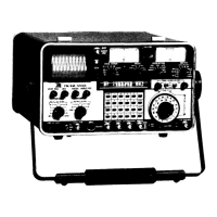
IFR FM/AM-1200A

IFR FM/AM-1200A
294 pages
To Next Page IconTo Next Page
To Previous Page IconTo Previous Page
Loading...
~
'
,
4-5
RECEIVER
OPERATION
3
4
18
22
23
24
25
26
27
28
29
30
32
35
39
40
41
4-2
8
02
FM/AM-1200S/A
CONNECTORS
AND
INDICATORS
APPLICABLE
TO
RECEIVER
OPERATION:
1
MODULATION
Meter
11
T/R
Connector
15
EXT
MOD/SINAD
Connector
16
DEMOD
Connector
20
SCOPE/DVM
Connector
31
CRT
Display
34
ANT
Connector
36
FREQ
ERROR
Meter
37
V
FD
Figure
4-1 FM/AM-1200S/A
Front
Panel
Controls
Applicable
to
Receiver
Operation
CONTROL
SETTING
MODULATION
Select
Control
As
req
1
d
Modulation
METER
Control
As
re
q
1
d
Keyboard
As
req
1
d
PWR/OFF/BATT
Switch
"PWR"
or
"BATT"
Scope
VERTICAL
Attenuator
As
req
1
d
Vernier
Control
VERTICAL
Attenuator
As
req
1
d
Selector
Control
Scope
HORIZONTAL
Sweep
As
req
1
d
Vernier
Control
HORIZONTAL
Sweep
As
reo
1
d
Selector
Control
VERT
POS
Control
As
re
q
1
d
INT
Control
As
req
1
d
FOCUS
Control
As
req
1
d
HORIZ
POS
Control
As
req
1
d
GEN/LOCK
Control
Full
ccw,
FREQ
ERROR
Meter
As
req
1
d
Range
Selector
Control
MODE
Selector
Control
"REC"
VOLUME
Control
As
req
1
d
Squelch
Control
As
req
1
d
Table
4-3 FM/AM-1200S/A
Front
Panel
Controls
Appl
i
cable
to
Receiver
0 per
at
ion
detent
~

Table of Contents