EasyManua.ls Logo

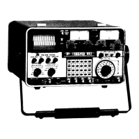
IFR FM/AM-1200A

IFR FM/AM-1200A
294 pages
To Next Page IconTo Next Page
To Previous Page IconTo Previous Page
Loading...
SIGNAL
CHARACTERISTIC(S):
MONITORING
DEVICE(SJ:
CONTROL
SETTINGS:
Transmitter
Power
(WATTS)
MODULATION
Meter
( 1 )
Modulation
Meter
(T/R
Connector
(
11
)
only
l
Control
( 4 )
to
or
desired
"WATTS"
selection.
VFD
( 3
7)
Depress
"2nd
FUNCT"
and
"METER"
Keys
( i n
that
Ot'der).
CRT
Display
( 3 1 )
(Spectrum
Analyzer
on
HORIZONTAL
Sweep
FM/AM-12005
only
J
Selector
Control
( 2 6 )
clockwise
to
1
MHz/DIV
or
l e s s .
Relative
Signal
MODULATION
Meter
( 1 )
Modulation
METER
Strength
Control
( 4 )
to
"S I G ...
VFD
( 3
7)
Depress
"2nd
FUNCT"
and
"METER"
keys
( i n
that
order)
Table
4-4
Receiver
Monitoring
Capabilities
(Cont'dl
4-5-2
BASIC RECEIVER
OPERATION
Basic
operation
of
the
FM/AM-1200S/A
receiver
is
as
follows:
STEP
PROCEDURE
1.
If
signals
are
to
be
monitored
"off-the-air",
connect
external
antenna
to
ANT
Connector
(34);
if
signals
are
to
be
received
by
direct
cable
connection,
apply
signal
to
T/R
Connector
(11).
4-30
06
!CAUTION!
MAXIMUM
CONTINUOUS
INPUT
TO
ANTENNA
CONNECTOR
(34)
MUST
NOT
EXCEED
0.25
WATTS.
MAXIMUM
INPUT
TO
T/R
CONNECTOR
(11)
MUST
NOT
EXCEED
150
WATTS.
150 w
50 w
1
minute
"ON". 5
minutes
"OFF".
Maximum
continuous.
lNOTEI
For
Accurate
Power
Meter
measurements,
set
RF
Level
Attenuator
Control
(9)
to
any
position
other
than
-20
dBm

Table of Contents