TRADUCTION OF THE ORIGINAL INSTRUCTIONS FOR USE
BS 400/60 AFI-Eing ED.2011 rev.00 28/60
ring – 1/RI0182 - and possibly adjust or replace it.
Clean the machine WEEKLY, lubricate all joints and surfaces in contact with oil or grease. Make sure that there is
oil in the hydraulic unit tank while the saw is off: remove the plug and check that the oil reaches up to 3 cm from the
edge. heck the oil level in the gearbox: with the sawframe all the way down, it must reach the oil window on the side
of reduction box.Nel caso si debba sostituire il cilindro procedere nel seguente modo: (riferirsi alla tavola 7/11 dis.
RI0171)
a macchina spenta svitare e togliere il raccordo in posizione A, operando dal dietro della macchina con chiave da
24mm, svitare e togliere il grano B , svitare i 3 grani della ghiera C, sfilare un poco il cilindro e aprire il SEEGER D.
Staccare il raccordo E prima di togliere il cilindro completo in direzione F.
Per il rimontaggio eseguire in ordine inverso le operazioni precedenti.
Verificare che il totalizzatore G segni zero quando il cilindro è tutto in avanti, altrimenti svitare il granino posto sul
collare del totalizzatore e girare il collare fino ad avere zero ; fissare il granino
Verificare che il finecorsa H venga schiacciato dalla vite I sia quando la ghiera L è tutta avvitata, sia quando e’
tutta svitata.
10.7 - POSIZIONE COMANDO -solo per versioni elettroniche -allentare le maniglie poste alle due estremita'
del braccio porta comando ( es.pos.2/fig.RI0176) per ruotare liberamente il comando durante le fasi di
programmazione e bloccarle durante il funzionamento automatico.
Non svitare MAI completamente la maniglia soprastante il pannello di comando.
1
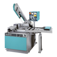
Replace the coolant MONTHLY and clean the tank. Ensure that all screws and bolts since they may have loosened.
Make sure that stroke-ends and switches work properly; check the leads, tubes and hydro-pneumatic connections;
make sure that seldom-used devices work properly. Check the two blade guides and the hard metal pads inside,
adjust and possibly replace them (drawing RI0372).
Once a YEAR - or after 2000 working hours - replace the oil in the gearbox, as shown in the chapter MACHINE
RUN IN.
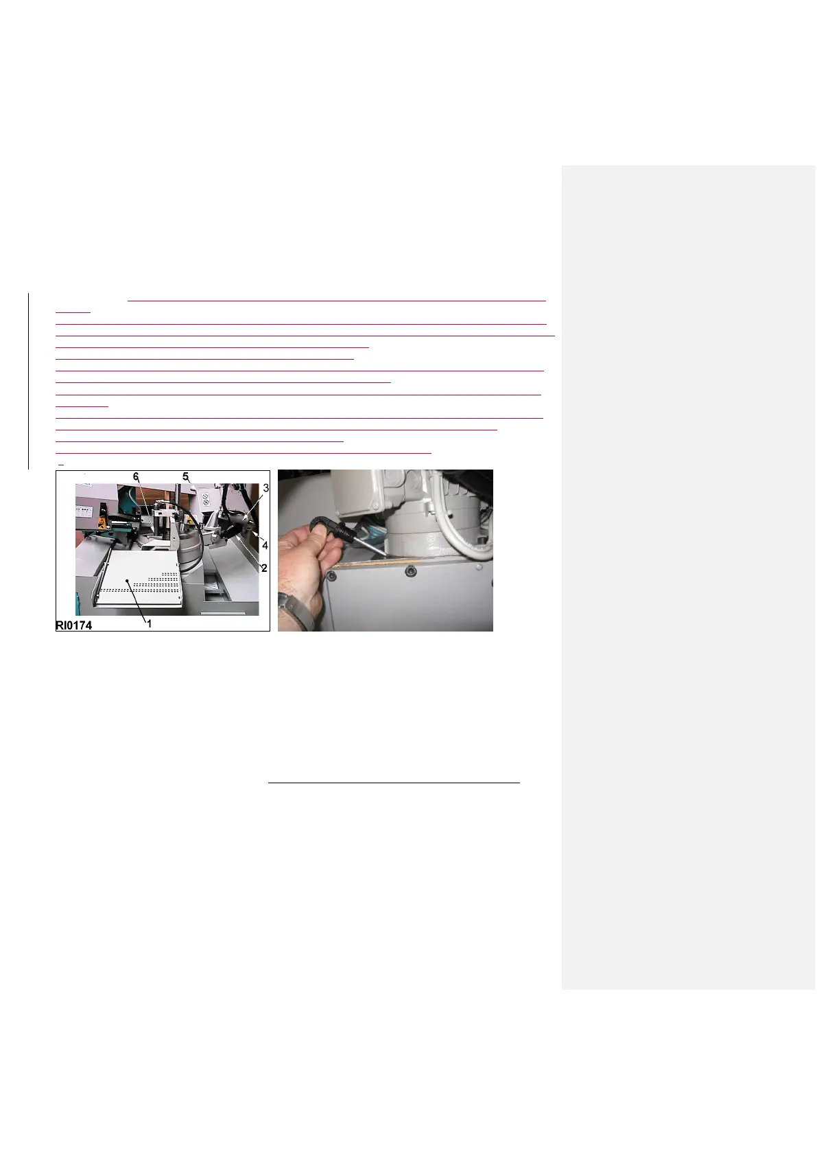
17.2 - BLADE REPLACEMENT
– drawing RI0177 This is the most frequent maintenance operation, due to the natural deterioration of the blade; it is
essential to replace it correctly and safely. With the sawframe up and at 0°, power off: open the blade guard - pos. 1
- and lift it, loosen the blade tension device by means of the front screw. Remove first the blade from the pulleys -
pos. 2/3 - then from the blade guides – pos. 4/5 - using protective gloves while carrying out these operations.