TRADUCTION OF THE ORIGINAL INSTRUCTIONS FOR USE
BS 400/60 AFI-Eing ED.2011 rev.00 27/60
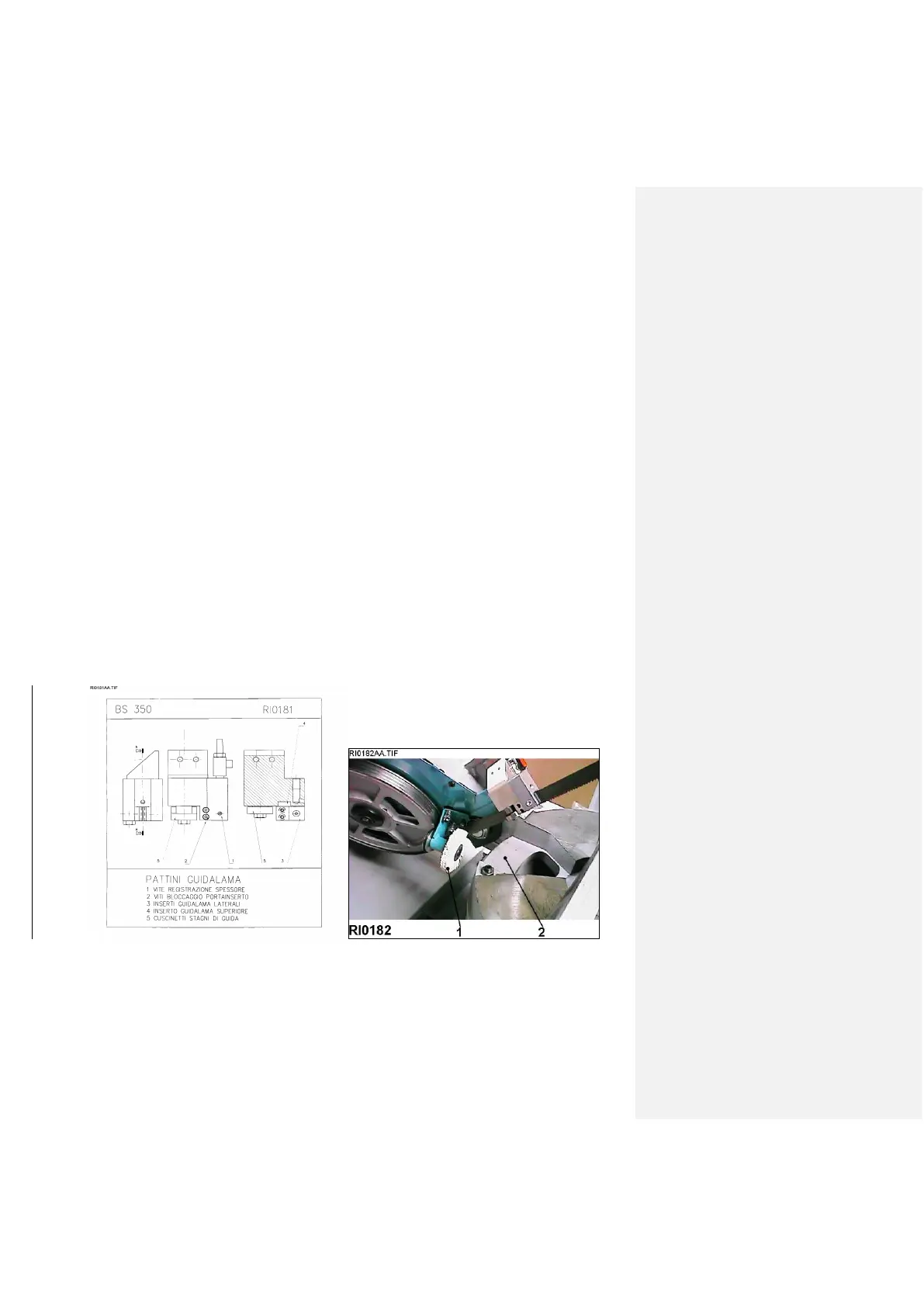
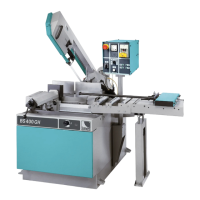
The lateral pads are mechanically fixed and each can be replaced without removing the whole blade guide, just by
loosening completely the two screws – 2/RI0181. By removing both lateral pads, the special upper pad which is in
contact with the blade can be removed.
BLADE - Check the perpendicularity between blade and worktable: this is very important and, along with the
blade tension, it assures straight cuts. Check it the following way: with the sawframe up and at 0° and the vice
completely open, put a square at 90° on the worktable (close to the supporting jaws) and very close to the blade.
While keeping the square still, lower the sawframe until reaching the end-cut point and evaluate if the blade
gets closer to it or farther. Lift the sawframe, move the square towards the operator so that the blade is
close to the higher extremity of the square, then lower the sawframe again until reaching the end-cut point
while always keeping the square still.
Usually this test allows to single out geometrical errors, but it is even more important in order to ensure that, in case
of not perfectly perpendicular cuts, the reason is not linked with factors external to the machine (for example, blade
in a bad condition, wrong tension, wrong tooth pitch, excessive pressure during the cut).
SPRINGS – It may be necessary to modify the tension of the return springs – 6/RI0464 – located in the back of the
sawframe. Loosen the fixing screws of the floating plate and, by turning the back screw, position them in their slots.
Tighten strongly the screws.
It is recommended to carry out this procedure while the sawframe is all the way up. If you have problems doing it,
you can lower the back stop screw before tensioning the spring, and then put it back in the original position.
CUTTING SPEED - Rotate the handle – 12/RI0464 – from 0 to the maximum level to increase the down-feed
speed: any variations should be made considering the type, shape and size of the material, the blade speed and
life, the coolant, and so on.
VICE PRESSURE - Additional valves to reduce the vices clamping pressure can be assembled in case the material
could deform. Since they are modular, they do not require any adjustments and can be assembled at any time, one
below each vice.
FEEDER - The feeding speed when forwarding the material (and during the return) is linked with the inverter
functions.If the feeding times are much different than normally (max. 14 seconds for a complete stroke forward and
backward, each one of 500mm), check if there are mechanical interferences or rollers alignment problems.
17 – MAINTENANCE – for the user
Regularly carry out maintenance operations as described below to maintain unchanged the machine safety devices
and technical features of the saw.
17.1 PERIODICAL MAINTENANCE
To be carried out DAILY or more often if the machine is doing a heavy job. Remove the chips from the machine
conveying the smallest ones into the chip tray – 5/RI0464. Remove and empty the chip tray; add coolant if
necessary; check the wear of the saw blade and replace it if necessary; check the blade brush and the transmission