TRADUCTION OF THE ORIGINAL INSTRUCTIONS FOR USE
BS 400/60 AFI-Eing ED.2011 rev.00 17/60
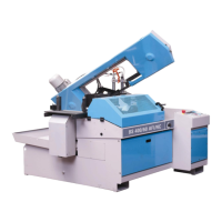
13.1 - COOLANT
Prepare the coolant by mixing cutting oil and water (the tank capacity is about 60 liters) in proportion 1/10, 1/15 or
according to the instructions provided by the supplier. Pour in the coolant in the tank – accessible in the back side of
the floor stand - or directly on the work table. In this case make sure that the chip tank is correctly placed.
13.2 – PNEUMATIC CONNECTION (OPTION, IF THE MINIMAL LUBRICATION SYSTEM IS APPLIED)
The bandsaw is provided with reducer + air lubricator, but it’s recommended to connect it to a system to unload
condensate, with cables correctly installed and a pressure of at least 5/6 BAR. The air consume is about 1 NI for
each cycle.
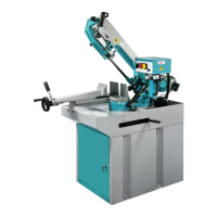
13.3 - ELECTRICAL CONNECTION
Verify that voltage and power frequency are compatible with the figures shown in the technical data plate (placed on
the right side of the floor stand); a difference over 10% causes some working troubles.
This operation must be performed by authorized operators (i.e. by an electrician ). The phasing performed
by the manufacturer allows to get a right rotation of all motors by connecting the wires in the following
order L1=R, L2=S, L3=T, N=neutral wire;
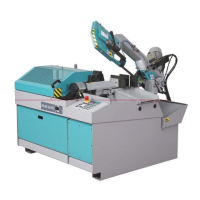
Anyhow check what follows (with the blade protection closed):
a) If the EMERGENCY- button is on , press it off and turn it 1/4 of turning in the marked direction.
b) press the button ON of the main switch-pos.13/RI0464- , placed on the column of the rear side of the machine ;
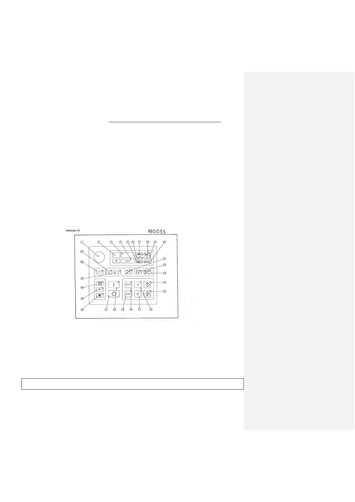
some leds of the control panel of the control are flashing-pos.6/ RI0055 - and the display shows some numbers
and/or figures.
c) push the button “CLOSED VICES” - pos. 19 / dr. RI0055 - for starting the motor of the hydraulic unit
and check if the saw frame moves up and down when you push the corresponding buttons - pos. 16 or
17 / dr. RI0055;
d) if it does not happen in the first 10 seconds turnf off the machine by switching off the main switch and check the
connection with the line .( disconnect the feeding plug , reverse the connection of two of the wires of line
connection , excluding the green / yellow cable of grounding and start again from point a) .
e) Be sure that coolant is sucked in by the tank and arrives in the cutting area. ( with the taps open, by pressing the
button -pos.23/dr.RI0055- the recycling pump brings into action ).
f) Stop the working by pressing the main switch-pos.13/dr.RI0464.
If you do not push any other button within 10 minutes, the electronic control deactivates the oil pump - in hydralic
models -, or it stops the compressed air - in the hydropneumatic models-. For starting up the system push again the
button -pos..19/dr.RI0055- (=Close the vice) the display shows for an instant a series of led lights-.
In case an external voltage transformer is supplied, be sure to place it in a safe position, far from the material
loading/unloading areas.
14 - BAND TENSIONING
The machine is equipped with a tensioned band (the starting of the motor is impossible if right force of tension has
not been opened up before ). . If it is not so, before tensioning the band we suggest to check as follows: