TRADUCTION OF THE ORIGINAL INSTRUCTIONS FOR USE
BS 400/60 AFI-Eing ED.2011 rev.00 23/60
Lock the small screw – 2/RI0468 – located over the main screw, in order to prevent the vice from opening
while the saw is running. Position the forward blade guide – 8/RO0464 – so that it doesn’t collide with the
bar or the jaws when the sawframe drops.
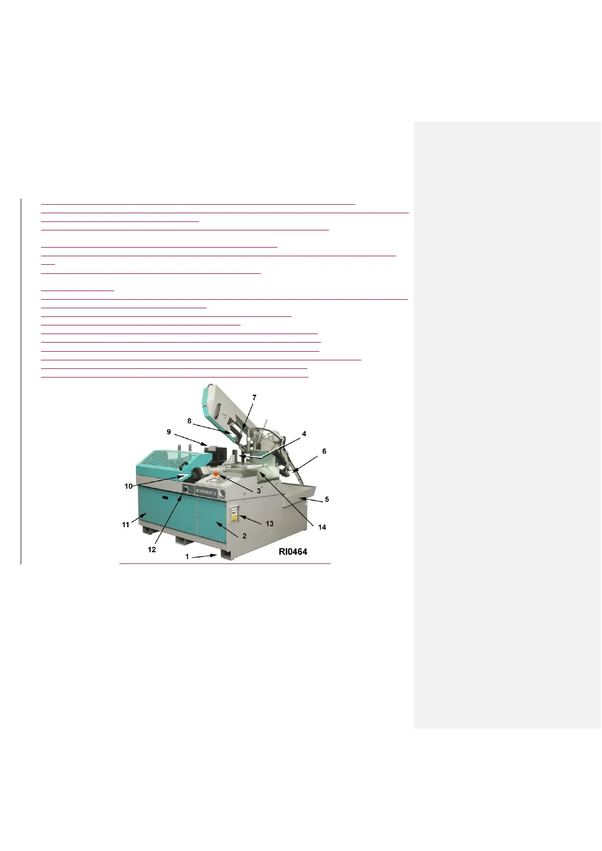
I dispositivi di sezionamento dall'energia esterna sono sul lato posteriore della colonna di sostegno:
* interruttore generale lucchettabile con protezione magnetica e termica di tutto l'impianto, completo di dispositivo di
sgancio per cadute di tensione -pos.1/fig.RI0183-,
* la combinazione spina + presa collegata al cavo di alimentazione (a cura dell'utilizzatore).
Il quadro comandi -fig.RI0055- montato su braccio orientabile, comprende:
1)-emergenza; blocca tutti i dispositivi elettrici quando viene azionata. Per il ripristino ruotare il pulsante di 1/4 di
giro.
2)-pannello di controllo con display ( vedi paragrafo 9.1 = TASTIERA)
Gli altri comandi sono :
3)- Interruttore generale lucchettabile con protezione magnetica e termica di tutto l'impianto, completo di dispositivo
di sgancio per cadute di tensione -pos.1/fig.RI0183-
4)- maniglia a ripresa per bloccaggio braccio porta comando -pos.2/fig.RI0183-
5)- regolatore idraulico della velocita' di taglio -pos.1/fig.RI0184
6)- sbloccaggio/bloccaggio rotazione piano di lavoro per tagli inclinati -pos.1/fig.RI0178-
7)- rubinetti del circuito di refrigerazione, montati sui pattini guidalama -pos.2/fig.RI0178-
8)- sbloccaggio/bloccaggio asta porta guidalama anteriore scorrevole -pos.3/fig.RI0178-
9)- volantino di apertura/chiusura morsa (a scorrimento rapido, vedi paragrafo 9.5) -pos.4/fig.RI0178-
10)- presa a parete per sincronismo con apparecchiatura esterna -pos.3/fig.RI0183-
11)- rubinetto per il circuito di lubrificazione con pistola di lavaggio -pos.4/fig.RI0183-
15.6 - SEMIAUTOMATIC CYCLE
Place the material so it goes over the cutting line, then lock it, select the motor speed , the working, the coolant
delivery and start the cycle with the button START CYCLE- pos.20/dr.RI0055. Adjust the coolant flow that reaches
the band and after the rapid approaching start the descent by planning the speed with the control(8).
At the cutting end the band goes up again and the semiautomatic cycle finishes.
Thanks to the versatility of the electronic control, the main here described cycle can be changed as regards to the
working to do.
15.7 - ESC ( Electronic Speed Control - if it is installed )
As the motor is running, increase or decrease the speed by pushing the button (+/2) - pos.13/RI0055 - or (-/1) -
pos.11/RI0055 – on the display you can read the current speed.
In case the maximum power supply threshold is exceeded - for example, because of an excessive cutting pressure
or because the blade remains stuck into the material - the Inverter stops the motor and the error message “Er0025”
appears on the display. To restore it, the main switch has to be turned to 0 (OFF), wait for about one minute and
then turn it on I (ON).