30
INSTALLER
USERMAINTENANCE TECHNICIAN
TECHNICAL DATA
A
B
A
C
29
Ducting
ADAPTOR
(A) mm
SHAFT
(B) mm
SHAFT
(C) mm
Ø 80
Rigid
86 126 146
Ø 80
Flexible
90 130 150
1
2
3
3
4
5
6
7
6
8
9
A
10
11
12
30
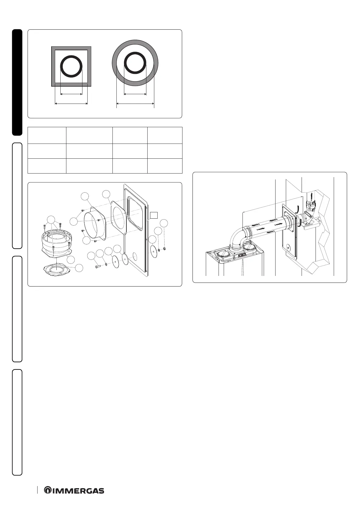
e adapter kit includes (Fig. 30):
No.1 Door adaptor Ø 100 or Ø 125 (1)
No.1 Door gasket made of neoprene (2)
No.4 Screws 4.2 x 9 ST (3)
No.1 Hex headed screw M6 x 20 (4)
No.1 Flat nylon washer M6 (5)
No.2 Door hole closure metal-sheet plate plug (6)
No.1 Plug gasket made of neoprene (7)
No.1 Toothed washer M6 (8)
No.1 M6 nut (9)
No.1 (kit Ø 80/125) Concentric gasket Ø 60/100 (10)
No.1 (kit Ø 80/125) Flanged adapter Ø 80/125 (11)
No.4 (kit Ø 80/125) Hexagon-head screws M4 x 16 at-tip screwdriver
(12)
No.1 (kit Ø 80/125) Bag of lubricating talc
Supplied separately (Fig. 30):
No.1 Ducting kit door (A)
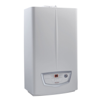
Technical data
e dimensions of the shas must ensure a minimum gap betwe-
en the outer wall of the smoke duct and the inner wall of the sha:
30 mm for circular section shas and 20 mm in the event of a
square section sha (Fig. 29).
Maximum 2 changes of direction are allowed on the vertical
section of the ue system with a maximum clearance angle of 30°
with respect to the vertical.
e maximum vertical extension using a Ø 80 ducting system is
27 m, the maximum extension includes 1 Ø 60/100 to Ø 80/125
adapter, 1 87° Ø 80/125 bend, 1 m of horizontal pipe Ø 80/125, 1
90° Ø 80 ducted bend and the roof terminal for ducting.
To determine the C92 ue system in congurations other than
that described (Fig. 31) one must consider the following head los -
ses:
- 1 m of concentric pipe Ø 80/125 = 1 m of ducted pipe;
- 1 87° bend = 1.4 m of ducted pipe;
Consequently one must subtract the equivalent length of the part
added to the 27 m available.
C92
X
31