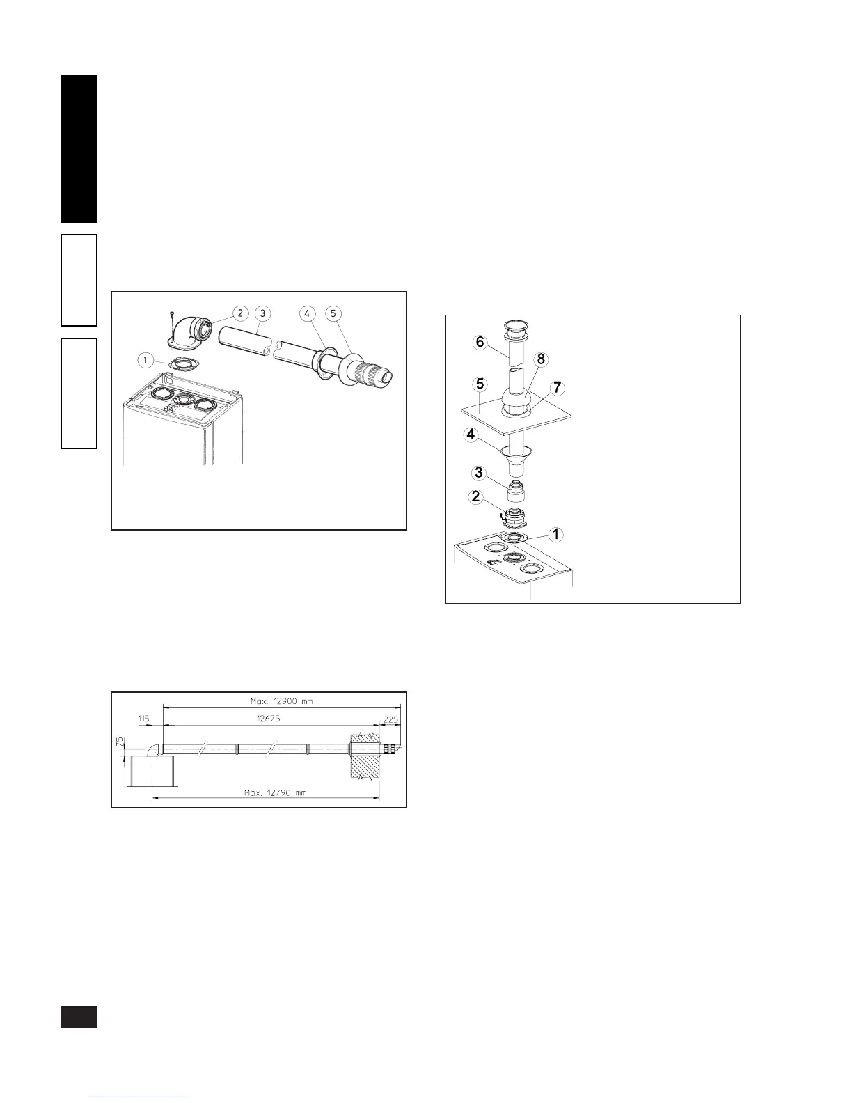
Horizontal intake kits - exhaust Ø 60/100.
Kit assembly: install the bend with ange (2) on the central
hole of the boiler inserting the seal (1) (which does not require
lubrication), positioning it with the round protrusions down-
wards in contact with the boiler ange and tighten using the
screws supplied with the kit. Fit the male end (smooth) of
the Ø 60/100 concentric terminal pipe (3) up to the stop
on the female end of the bend (2), making sure the relevant
internal and external rings are tted; this will ensure hold
and joining of the elements making up the kit.
N.B.: for correct operation of the system the terminal with
grill must be correctly installed, respecting the indication
“top” on the terminal.
• Coupling extension pipes and concentric elbows Ø 60/
100. To install possible coupling extensions on other fume
extraction elements, proceed as follows: t the male end
(smooth) of the concentric pipe or concentric elbow up to
the stop on the female end (with lip seals) of the previously
installed element; this will ensure correct hold and joining
of the elements.
e Ø 60/100 kit can be installed with the rear, right side,
left side and front outlet.
• Extensions for horizontal kit. e horizontal intake-ex-
haust kit Ø 60/100 can be extended up to a max. horizontal
length of 12.9 m, including the grill terminal and excluding
the concentric bend leaving the boiler. is conguration
corresponds to a resistance factor of 100. In this case special
extensions must be requested.
N.B.: when installing the ducts, a section clamp with pin
must be installed every 3 metres.
• External grill. N.B.: for safety purposes, do not even
temporarily obstruct the boiler intake/exhaust terminal.
Vertical kit with aluminium tile Ø 60/100.
Kit assembly: install the concentric ange (2) on the central
hole of the boiler inserting the seal (1) (not requiring lubrica-
tion), positioning it with the round protrusions downwards
in contact with the boiler ange and tighten using the screws
supplied with the kit. Fit the male end (smooth) of the
adapter (3) in the female end of the concentric ange (2).
Fake aluminium tile installation: replace the tiles with the
aluminium sheet (5), shaping it to ensure that rainwater runs
o. Position the xed half-shell (7) on the aluminium tile
and insert the intake/exhaust pipe (6). Fit the male end (6)
(smooth) of the Ø 60/100 concentric terminal up to the stop
on the female end of the adapter (3) (with lip seals), making
sure that the ring (4) is already tted; this will ensure hold
and joining of the elements making up the kit.
• Coupling extension pipes and concentric elbows. To install
possible coupling extensions on other fume extraction ele-
ments, proceed as follows: t the male end (smooth) of
the concentric pipe or concentric elbow up to the stop on
the female end (with lip seals) of the previously installed
element; this will ensure correct hold and joining of the
elements.
Important: if the exhaust terminal and/or extension con-
centric pipe needs shortening, consider that the internal
duct must always protrude by 5 mm with respect to the
external duct.
is specic terminal enables fume exhaust and air intake
necessary for combustion, in a vertical direction.
N.B.: the vertical kit Ø 60/100 with aluminium tile enables
installation on terraces and roofs with maximum slope of
45% (24°) and the height between the terminal cap and
half-shell (374 mm) must always be respected.
C13x
C13x
C33x
e kit comprises:
1 - Seal (1)
1 - Concentric bend Ø 60/100 (2)
1 - Concentric intake/exhaust
terminal Ø 60/100 (3)
1 - Internal ring (4)
1 - External ring (5)
e kit comprises:
1 - Seal (1)
1 - Female concentric ange (2)
1 - Adapter from 80/125
to 60/100 (3)
1 - Ring (4)
1 - Aluminium tile (5)
1 - Intake/exhaust concentric
pipe Ø 60/100 (6)
1 - Fixed half-shell (7)
1 - Movable half-shell (8)
10
INSTALLERUSERTECHNICIAN