e vertical kit with this conguration can be extended to a
max. vertical length of 13.4 m, including the terminal. is
conguration corresponds to a resistance factor of 100. In
this case specic extensions must be requested.
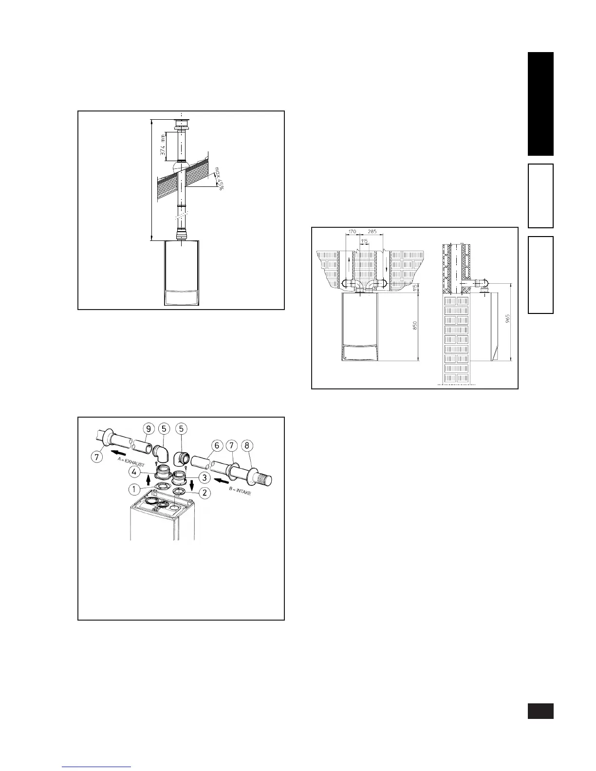
Separator kit Ø 80/80. e separator kit Ø 80/80, enables
separation of the exhaust ues and air intake pipes accord-
ing to the layout shown in the gure. Fumes are expelled
from duct (A) (strictly in plastic material resistant to acid
condensates). Air is taken in through duct (B) (also in plastic
material) for combustion. Intake duct (B) can be installed
either on the right or left hand side of the central exhaust
duct (B). Both ducts can be oriented in any direction.
• Assembly of separator kit Ø 80/80. Install the ange (4)
on the central hole of the boiler inserting the seal (1)
(which does not require lubrication), positioning it with the
round protrusions downwards in contact with the boiler
ange and tighten using the screws supplied with the kit.
Remove the at ange on the lateral hole (depending on
installation requirements) and replace it with ange (3)
inserting seal (2) already tted on the boiler and tighten
using the screws supplied. Insert bends (5) with the male
end (smooth) in the female end of the anges (3 and 4).
Fit the male end (smooth) of the intake terminal (6) up to
the stop on the female end of the bend (5), making sure
that the relevant internal and external rings are tted. Fit
the male end (smooth) of the exhaust pipe (9) up to the
stop on the female end of the bend (5), making sure that
the internal ring is tted; this will ensure hold and joining
of the elements making up the kit.
• Coupling of extension pipes and elbows. To install possible
coupling extensions on other fume extraction elements,
proceed as follows: t the male end (smooth) of the pipe
or elbow up to the stop on the female end (with lip seals)
of the previously installed element; this will ensure correct
hold and joining of the elements.
• Installation space. e previous gure gives the min.
installation space dimensions of the Ø 80/80 separator
terminal kit in several limit conditions.
• Extensions for separator kit Ø 80/80 e max. vertical
straight length (without bends) usable for Ø 80 intake
and exhaust pipes is 41 metres regardless of whether they
are used in intake or exhaust. e max. horizontal straight
length (with intake and exhaust bends) usable for Ø 80
intake and exhaust pipes is 36 metres regardless of whether
they are used in intake or exhaust.
N.B.: to favour the removal of possible condensate forming
in the exhaust pipe, incline the pipes towards the boilers
with a min. slope of 1.5% (see g.). When installing the Ø
80 ducts, a section clamp with pin must be installed every
3 metres.
e kit comprises:
1 - Exhaust seal (1)
1 - Flange seal (2)
1 - Female intake ange (3)
1 - Female exhaust ange (4)
2 - Bends 90° Ø 80 (5)
1 - Intake terminal Ø 80 (6)
2 - Internal rings (7)
1 - External ring (8)
1 - Exhaust pipe Ø 80 (9)