29
36
INSTALLERUSERMAINTENANCE TECHNICIAN
3
BOILER STARTUP
INITIAL CHECK.
To commission the boiler:
- ensure that the type of gas used corresponds to
boiler settings;
- check connection to a 230V-50Hz power
mains, correct L-N polarity and the earthing
connection;
- make sure the central heating system is lled
with water and that the boiler manometer
indicates a pressure of 1÷1.2 bar.
- switch the boiler on and ensure correct ignition;
- check the proper calibration of the number of
fan revolutions;
- check the CO
2
in the combustion products at
maximum and minimum ow rate;
- check activation of the safety device in the event
of no gas, as well as the relative activation time;
- check the intervention of the main switch lo-
cated upstream of the boiler and in the boiler;
- check that the intake and/or exhaust terminals
are not blocked;
- ensure activation of all adjustment devices;
- seal the gas ow rate regulation devices (if
settings are modied);
- ensure production of domestic hot water (when
the boiler is connected to an external storage tank
unit);
- ensure sealing eciency of water circuits;
- check ventilation and/or aeration of the instal-
lation room where provided.
Even if just one single safety check provides a
negative result, do not commission the system.
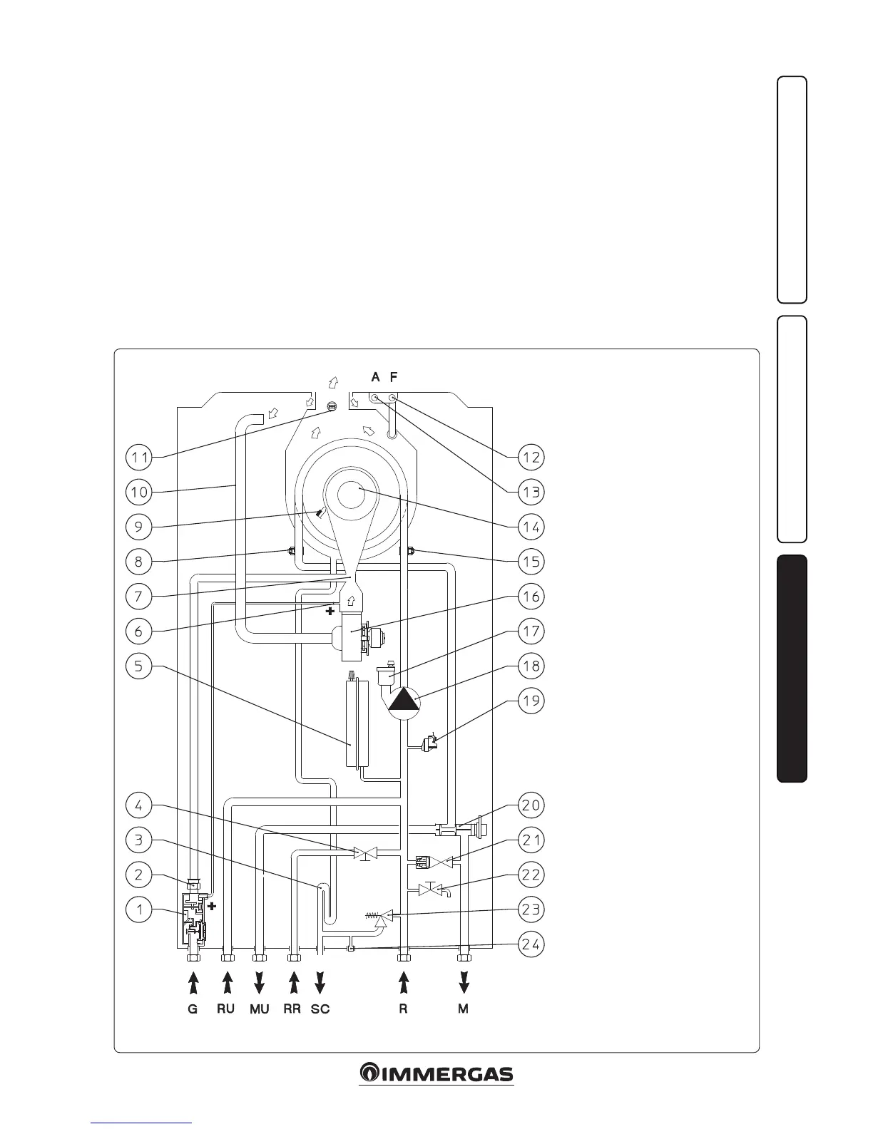
3.1 BOILER HYDRAULIC DIAGRAM.
Key:
1 - Gas valve
2 - Gas nozzle
3 - Condensate drain trap
4 - System lling valve
5 - System expansion vessel
6 - Positive (+) pressure point
7 - Venturi
8 - Flow probe
9 - Ignition/detection electrodes
10 - Air intake pipe
11 - Flue probe
12 - Flue sample point
13 - Air sample point
14 - Burner
15 - Return probe
16 - Fan
17 - Air vent valve
18 - Boiler pump
19 - Absolute pressure switch
20 - 3-way valve (motorised)
21 - By-pass
22 - System draining valve
23 - 3 bar safety valve
24 - 3 bar safety valve drain tting signal
G - Gas supply
RU - Storage tank unit return (optional)
MU - Storage tank unit ow (optional)
RR - System lling
SC - Condensate drain
M - System ow
R - System return