3
12
2
1
P1
P3
38
INSTALLERUSERMAINTENANCE TECHNICIAN
3.3 TROUBLESHOOTING
N.B.: maintenance interventions must be carried
out by an authorised company (e.g. Authorized
Aer-Sales Technical Assistance Service).
- Smell of gas. Caused by leakage from gas circuit
pipelines. Check sealing eciency of gas intake
circuit.
- Repeated ignition blocks. It can be caused by
no gas, check the presence of pressure in the
network and that the gas adduction cock is
open. Incorrect adjustment of the gas cock,
check the correct calibration of the gas valve.
- Irregular combustion or noisiness. It may be
caused by: a dirty burner, incorrect combustion
parameters, intake-exhaust terminal not cor-
rectly installed. Clean the above components
and ensure correct installation of the terminal,
check correct setting of the gas valve (O-Set
setting) and correct percentage of CO
2
in ue
gas.
- Frequent interventions of the safety thermostat
function (delegated to ow probe and system
return probe). It can depend on the lack of
water in the boiler, little water circulation in the
system or blocked pump. Check on the pressure
gauge that the system pressure is within estab-
lished limits. Check that the radiator valves
are not closed and also the functionality of the
pump.
- Siphon blocked. is may be caused by dirt or
combustion products deposited inside. Check,
by means of the condensate drain cap, that
there are no residues of material blocking the
ow of condensate.
- Heat exchanger blocked. is may be caused
by the drain trap being blocked. Check, by
means of the condensate drain cap, that there
are no residues of material blocking the ow of
condensate.
- Noise due to air in the system. Check opening
of the special air vent valve cap (Part. 18 Fig.
34). Make sure the system pressure and expan-
sion vessel pre-charge values are within the set
limits; e factory-set pressure values of the
expansion vessel must be 1.0 bar, the value of
system pressure must be between 1 and 1.2 bar.
3.4 CONVERTING THE BOILER TO
OTHER TYPES OF GAS.
If the boiler has to be converted to a dierent
gas type to that specied on the data nameplate,
request the relative conversion kit for quick and
easy conversion.
e gas conversion operation must be carried
out by an authorised company (e.g. Authorized
Aer-Sales Technical Assistance Service).
To convert to another type of gas the following
operations are required:
- remove the voltage from the appliance;
- replace the nozzle located on the gas valve and
gas/air mixing sleeve (Part. 8 Fig. 34), taking
care to disconnect the appliance during this
operation;
- apply voltage to the appliance;
- calibrate the number of fan revolutions (Parag.
3.5);
- adjust the correct air/gas ratio (Parag. 3.6);
- seal the gas ow rate devices (if adjusted);
- after completing the conversion, apply the
sticker, contained in the conversion kit, on the
data plate in the area relating to the type of gas.
ese adjustments must be made with reference
to the type of gas used, following that given in
the table (Par. 3.20).
3.5 CALIBRATION OF NUMBER OF FAN
REVS.
Attention: verication and calibration is neces-
sary, in the case of transformation to other types
of gas, in the extraordinary maintenance phase
with replacement of the PCB air/gas circuit com-
ponents or in the case of installations with ue
extraction systems, with horizontal concentric
pipe measuring more than 1 metre.
e boiler heat output is correlated to the length
of the air intake and ue exhaust pipes. is
decreases with the increase of pipe length. e
boiler leaves the factory adjusted for minimum
pipe length (1m coaxial).
- activate ue test (Parag. 3.12);
- detect the ue signal ∆P (Ref. 12 Fig. 34);
- compare the signal ∆P and, if necessary,
correct the S1 operating parameter with the
following table:
Victrix Tera 24 Plus
∆P > 200 Pa
G20 S1 = 126 (6300 rpm)
G31 S1 = 121 (6050 rpm)
Attention: check the serial number on the boiler.
From number 7211394 use the data in the fol-
lowing table.
Victrix Tera 24 Plus
∆P > 200 Pa
G20 S1 = 126 (6300 rpm)
G31 S1 = 120 (6000 rpm)
3.6 ADJUSTMENT OF THE AIRGAS
RATIO.
Attention: the CO
2
verication operations must
be carried out with the casing mounted, while the
gas valve calibration operations must be carried
out with the casing open and disconnecting the
boiler from the power supply.
Calibration of the CO
2
at minimum output
Enter the chimney sweep mode without with-
drawing DHW and set the output to minimum
(0%). To have an exact value of CO
2
the tech-
nician must insert the sampling probe to the
bottom of the sample point, then check that the
CO
2
value is that specied in the table, other-
wise adjust the screw (Part. 3 Fig. 38) (O-Set
adjuster). To increase the CO
2
value, turn the
adjustment screw (3) in a clockwise direction
and vice versa to decrease it.
Calibration of the CO
2
at maximum output
When you nish the minimum CO
2
adjustment,
while maintaining the chimney sweep function
active, set the output to maximum (99%). To
have an exact value of CO
2
the technician must
insert the sampling probe to the bottom of the
sample point, then check that the CO
2
value is
that specied in the table, otherwise adjust the
screw (Part. 12 Fig. 38) (gas ow rate regulator).
To increase the CO
2
value, turn the adjustment
screw (12) in a clockwise direction and vice versa
to decrease it.
At every adjustment variation on the screw 12 it
is necessary to wait for the boiler to stabilise itself
at the value set (about 30 sec.).
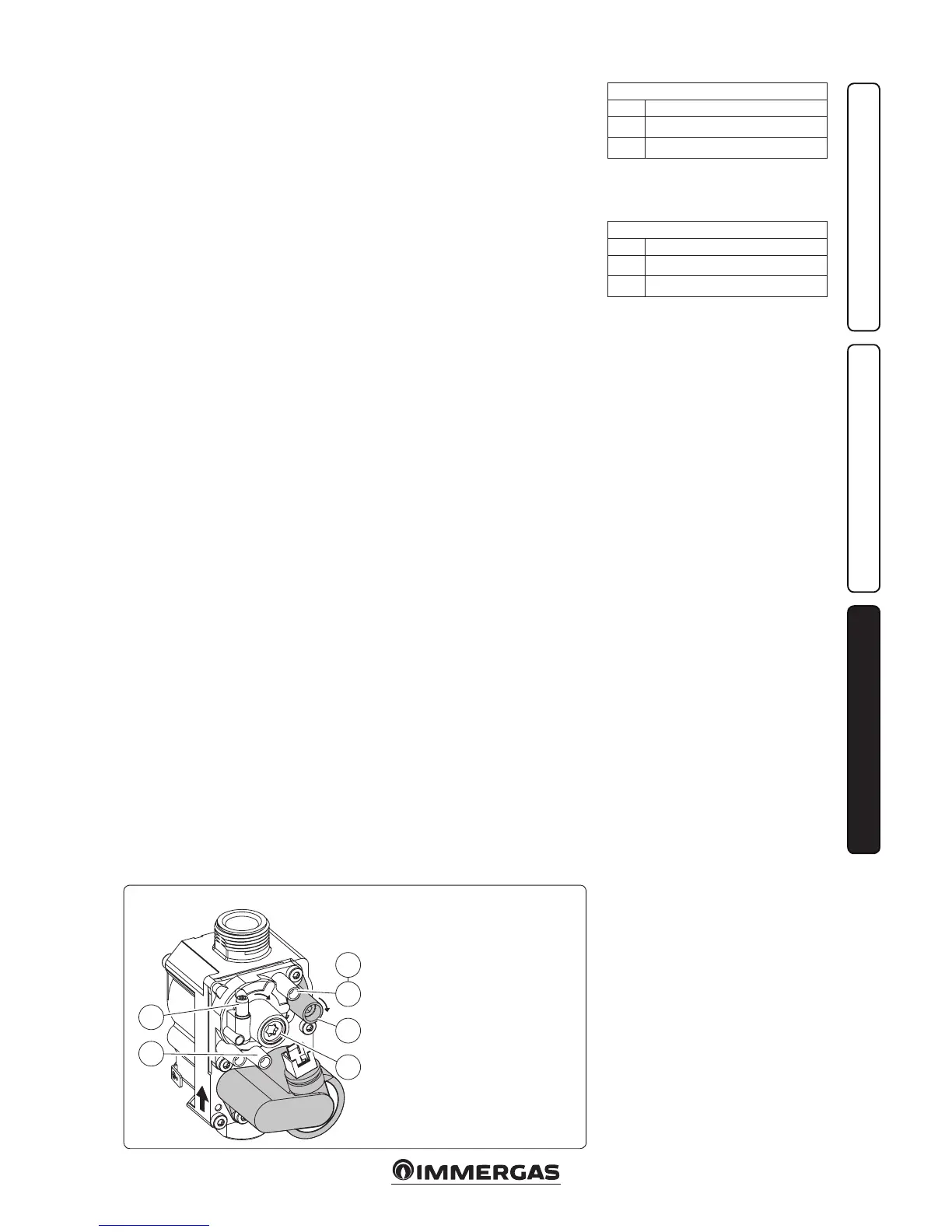
Key:
1 - Gas valve inlet pressure
point
2 - Gas valve outlet pressure
point
3 - O/Set adjustment screw
12 - Outlet gas ow rate
adjuster
42 Gas Valve