+
+
3
12
2
1
P1
P3
40
INSTALLERUSER
MAINTENANCE TECHNICIAN
45
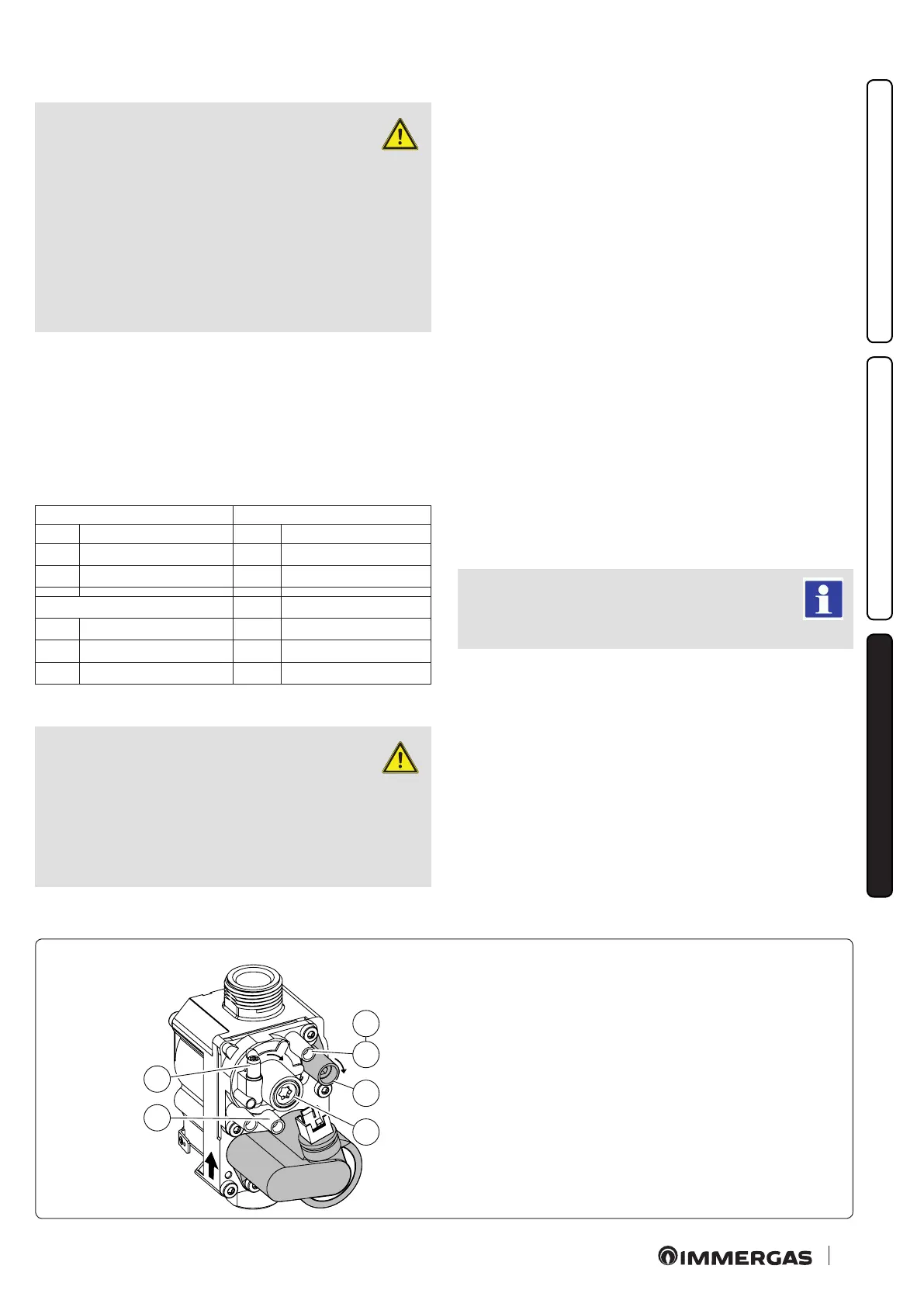
Key:
1 - Gas valve inlet pressure point
2 - Gas valve outlet pressure point
3 - O/Set adjustment screw
12 - Outlet gas ow rate adjuster
42 Gas Valve
Calibration of the CO
2
at minimum output
Enter the chimney sweep mode without withdrawing DHW and
set the output to minimum (0%). To have an exact value of CO
2
the technician must insert the sampling probe to the bottom of
the sample point, then check that the CO
2
value is that specied
in the table, otherwise adjust the screw (Part.3 Fig. 40) (O-Set
adjuster). To increase the CO
2
value, turn the adjustment screw
(3) in a clockwise direction and vice versa to decrease it.
Calibration of the CO
2
at maximum output
When you nish the minimum CO
2
adjustment, while maintain-
ing the chimney sweep function active, set the output to maximum
(99%). To have an exact value of CO
2
the technician must insert
the sampling probe to the bottom of the sample point, then check
that the CO
2
value is that specied in the table, otherwise adjust
the screw (Part. 12 Fig. 40) (gas ow rate regulator).
To increase the CO
2
value, turn the adjustment screw (12) in a
clockwise direction and vice versa to decrease it.
At every adjustment variation on the screw 12 it is necessary to
wait for the boiler to stabilise itself at the value set (about 30 sec.).
3.10 CHECKS FOLLOWING CONVERSION TO
ANOTHER TYPE OF GAS.
Aer making sure that conversion was carried out with a nozzle
of suitable diameter for the type of gas used and the settings are
made at the correct pressure, check that the burner ame is not
too high or low and is stable (does not detach from burner);
Maintenance interventions must be carried out by
an authorised company (e.g. Authorised Aer-Sales
Technical Assistance Service).
3.8 CALIBRATION OF FAN SPEED.
ATTENTION:
verication and calibration are neces-
sary, in the case of transformation to
other types of gas, in the extraordinary main-
tenance phase with replacement of the PCB,
air/gas circuit components or in the case of
installations with ue extraction systems, with
horizontal concentric pipe measuring more
than 1 metre.
e boiler heat output is correlated to the length of the air intake
and ue exhaust pipes. is decreases with the increase of pipe
length. e boiler leaves the factory adjusted for minimum pipe
length (1m coaxial).
- activate ue test (Parag. 3.15);
- detect the ue signal ∆P (Ref. 16 and 17 Fig. 38);
- compare the signal ∆P and, if necessary, correct the S1 operating
parameters with the following table:
Victrix Tera 28 1 Victrix Tera 32 1
∆P > 200 Pa ∆P > 200 Pa
G20 S1 = 126 (6300 rpm) G20 S1 = 134 (6700 rpm)
G31 S1 = 121 (6050 rpm) G31 S1 = 127 (6350 rpm)
Victrix Tera 38 1
∆P > 200 Pa
G20 S1 = 128 (6350 rpm)
G31 S1 = 130 (6400 rpm)
3.9 ADJUSTMENT OF THE AIRGAS RATIO.
ATTENTION:
the verication operations of the CO
2
must be carried out with the casing
mounted, while the gas valve calibration op-
erations must be carried out with the casing
open and removing the voltage from the boiler.
 Loading...


