16
STZSkW ed 12/07 ZEUS Superior kW
Technical DocumentationTechnical Documentation
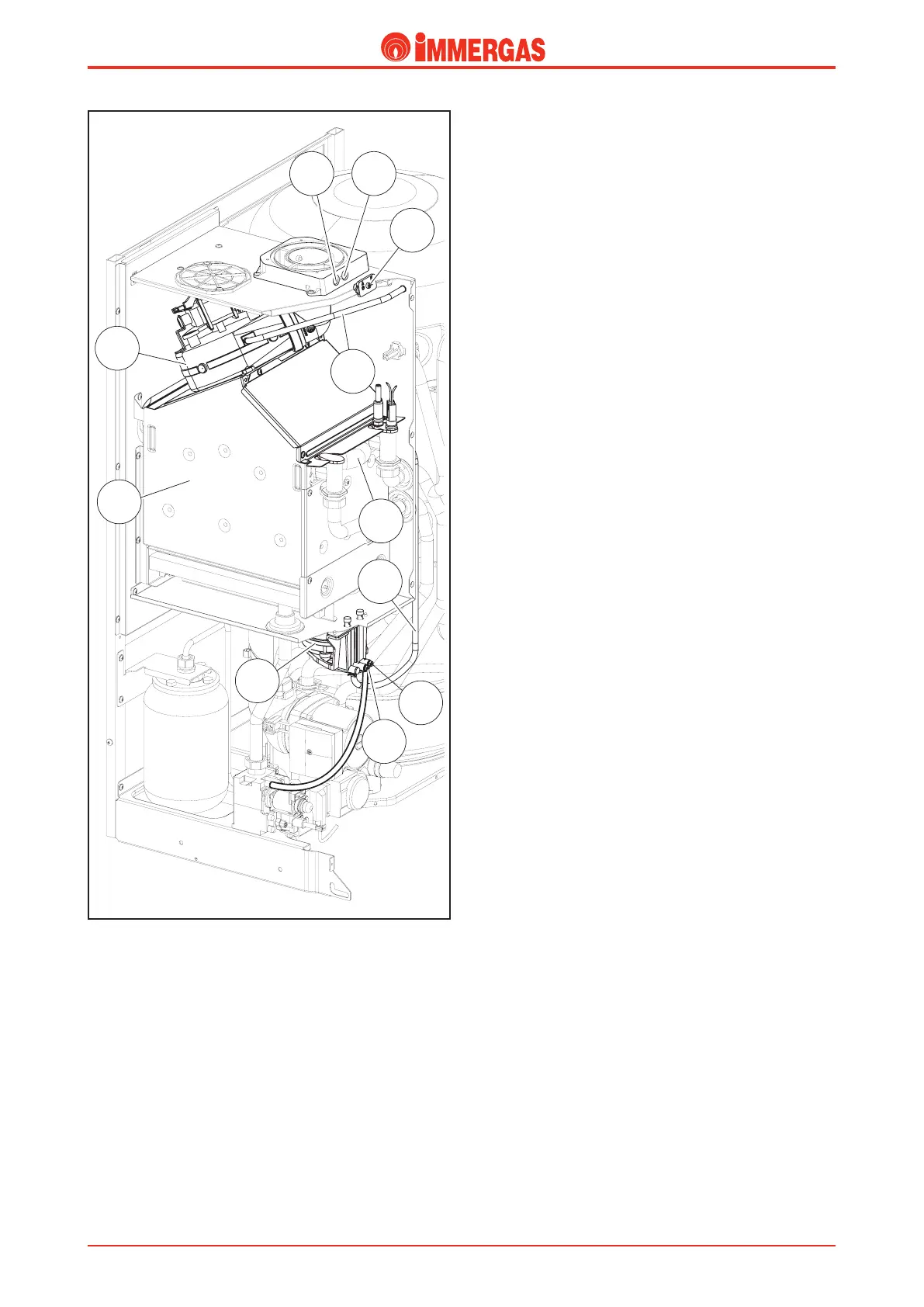
pipe (11) which is connected to the negative pressure point
of the ue pressure switch (6) and to the pressure point on
the fan.
e positive pressure point (10) is connected directly to the
inside of the sealed chamber.
Flue ow meter (6).
It is positioned in the lower external part of the sealed chamber
and detects, through the relevant point, the pressure dierence
between the inside of the fan (negative signal) and the inside
of the sealed chamber (positive signal).
e signal generated by the ue ow meter (6) is managed by
the circuit board in order to adjust fan speed (5), in a way to
maintain the pressure dierence constant at a value between
60 and 90 Pascal (between 6.1 and 9.2 mm. H
2
O), which can
be measured by the relevant pressure sockets (9-10).
When the pressure reaches the value set on the integrated
P.C.B. the burner can be ignited.
Fan (5).
e ue discharging fan operates downstream from the com-
bustion chamber and is physically installed on the upper part
of the ue hood (4) from where it extracts ue and directs
them to the ue system ducts the boiler is connected to. At
the same time, it ensures combustion air ow into the sealed
chamber.
e fan is controlled by the integrated P.C.B. and its function
essentially follows the burner operation.
Air/ue sample points (7-8).
ere are two sample points on the upper side of the sealed
chamber (they are accessible from the front), which can be used
to take samples of combustion air (7) and ue (8).
e two sample points are closed by one single plastic plug.
(13).
Flue pressure switch signal pressure points
(9-10).
In the lower external part of the sealed chamber, there are two
pres sure points, which can be used to verify the signal on either
end of the ue pressure switch (6).
e negative pressure point (9) is connected to a silicone