17
STZSkW ed 12/07 ZEUS Superior kW
Technical Documentation
Technical Documentation
Intake and exhaust systems.
(see intake and exhaust terminals instructions).
e ZEUS Superior kW boiler is arranged for connection to
the appropriate push-tting intake/exhaust pipes and can be
installed inside the home or outside the home (in a partially
protected place) in the following congurations.
Outdoors (in a partially protected place):
- sealed chamber and fan assisted with direct intake (type C)
using a compulsory upper cover kit (optional);
- with sealed chamber and forced draught (type C) using
the vertical or horizontal concentric kits, keeping the cap
mounted, without the obligation to use the upper cover
kit.
Indoors:
- open chamber and fan assisted (type B
22
) using a compulsory
upper cover kit (optional);
- sealed chamber and fan assisted (type C) using the vertical
or horizontal concentric kits or the Ø80/80 separator kit.
For that regarding the head losses relative to each accessory,
for the various combinations that can be performed, see the
instructions relative to the intake and exhaust terminals
(boiler instruction book).
e coupling of the accessories (curves, extensions, terminals)
is the push-tting type and sealing is ensured by appropriate
gaskets with silicone lip seals.
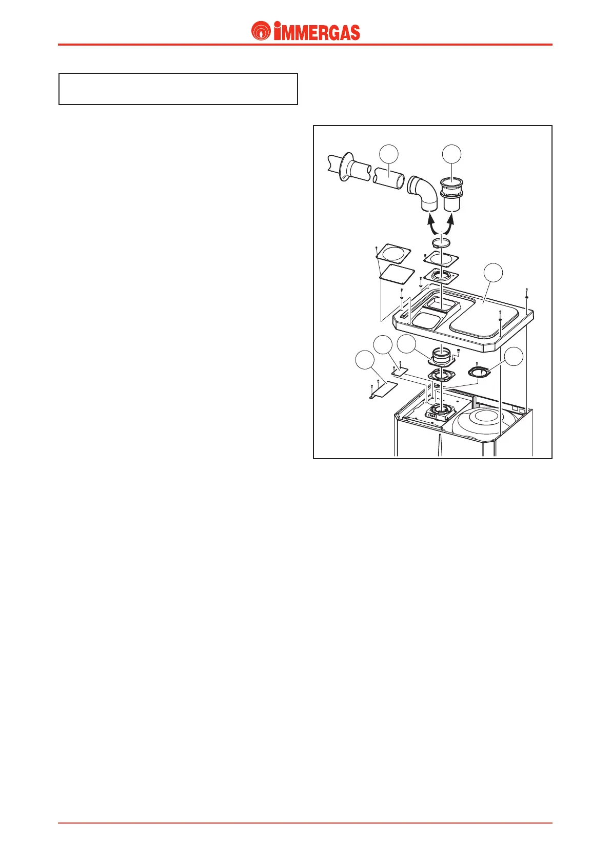
Sealed chamber and forced draught
conguration with direct intake for installation
outdoors in a partially protected place (see
gure at the side).
Using an appropriate cover (1) to be positioned on the upper
part of the sealed chamber, the boiler can be installed outdoors
in a partially protected place.
Intake.
Mounting of the cover (1) envisions the removal of the cap
(3) closing the hole present in the upper part of the sealed
chamber.
Attention:
For model 28 kW shaped sheet steel must be mounted (5)
instead of the cap (3).
For model 32 kW at sheet steel must be mounted (4) instead
of the cap (3).
e intake of combustion air takes place directly from the
environment making use of the free space between the lowerp
art of the cover (1) and the upper part of the boiler.
Exhaust.
e connection to the exhaust pipes with diameter of 80 mm
is obtained using the ange (2) used in the divided systems.
e use of the appropriate accessories aloows the horizontal
discharge (A) or vertical discharge (B).
To prevent condensate problems, the exhaust pipe must be
limited to 5 straight metres for normal pipes and 12 straight
metres for insulated pipes.
e maximum length accepted is 12 straight metres.
Open chamber and forced draught congura-
tion (type B
22
) for indoor installation (see gure
above).
e previously-described cover kit is used.
By removing the cap (3) present on the selaed chamber, air
intake takes place directly from the room in which the boiler
is installed.
e ues are discharged through special pipes wih a diameter
of 80 in an individual ue or directly to the outside.