18
STZSkW ed 12/07 ZEUS Superior kW
Technical DocumentationTechnical Documentation
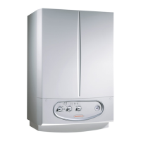
Sealed chamber and forced draught conguration
(type C).
Exhaust.
e connection to the exhaust pipes takes place using a ange
(1) or a anged bend to attach to the tting (4) present on the
upper part of the sealed chamber by placing a shaped gasket
between them (2).
e ange diers depending whether the divided or concentric
system is used.
In the rst case the passage for combustion air intake (5) is
closed while it is used in the second case.
Intake.
Using the divided system, the connection to the intake pipes
takes place in a similar way to the exhaust pipes, they being
connected to the hole with diameter of 80 mm (3) present in
the upper part of the sealed chamber.
If coaxial pipes are used, intake of the combustion air using
the concentric hole outsideof the exhaust tting (5).
Intake/exhaust kit.
e kits with relative accessories allow the use of four concentric
systems and two divided systems.
For that regarding head losses relative to each accessory, the
various combinations that can be carried out, follow the
instructions relative to the intake and exhaust terminals
(see boiler instructions book).
e coupling of the accessories (curves, extensions, terminals)
is snap-t type and sealing is ensured by the relevant silicone
lip seals.
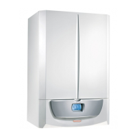
Ø 60/100 push-t horizontal concentric kit.
e ue duct (Ø 60 mm) is inserted directly in the intake
duct (Ø 100 mm).
Connect to the boiler using a 90° bend (2) which can be turned
and face any direction. Use the required extensions in order to
reach air and ue terminal (3).
Maximum allowable overall length without considering the
rst bend (2) is 3 straight horizontal meters.
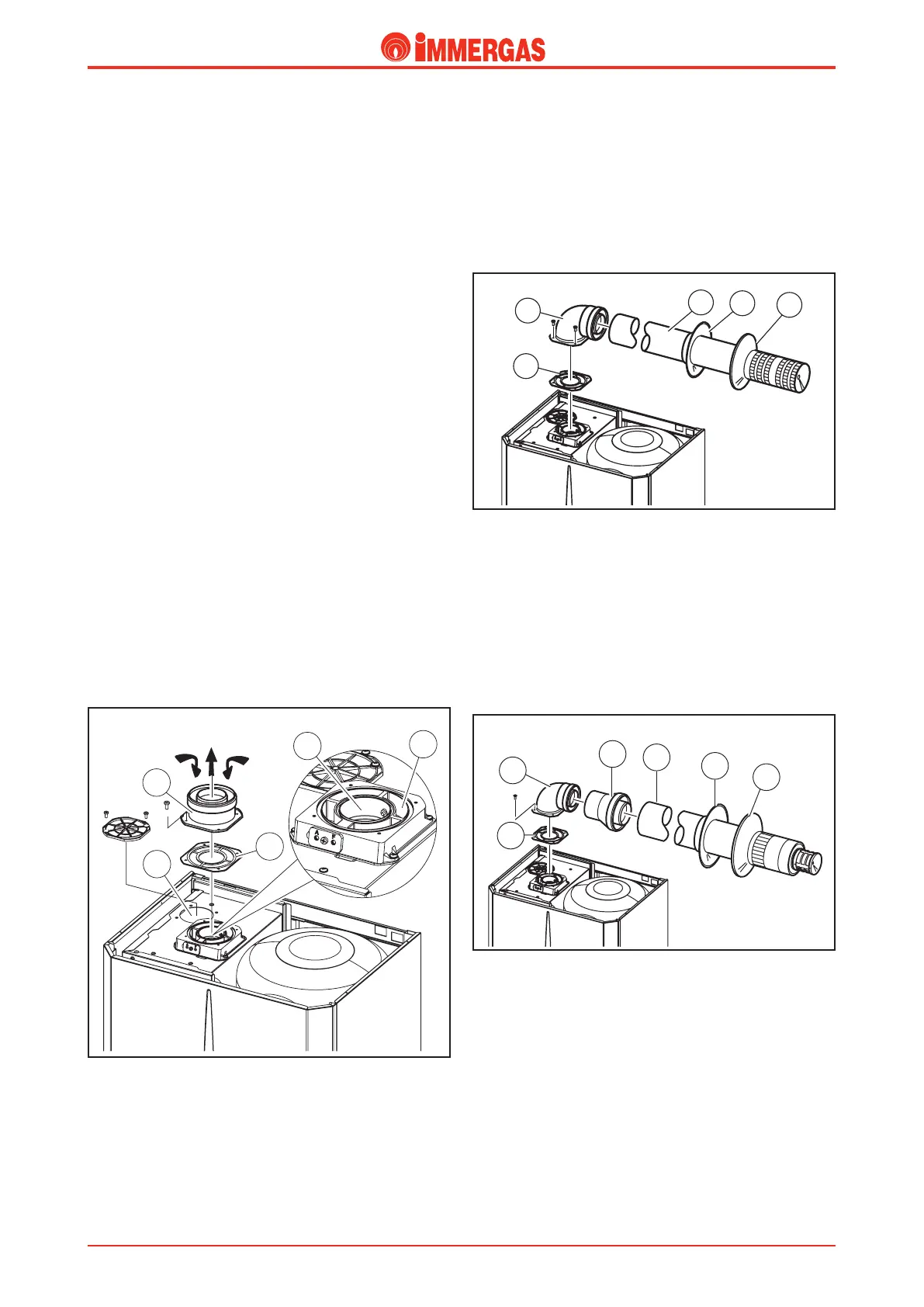
Ø 80/125 push-t horizontal concentric kit.
e ue duct (Ø 80 mm) is inserted in the intake duct (Ø
125 mm).
Connect to the boiler using a 90° bend with a 60/100 diameter
(2) which can be turned in order to face any direction. Using
the 60/100-80/125 adapter (3) and the appropriate extensions,
connect to the air and ue terminal (4).
Maximum allowed overall length without considering the rst
bend (2) is 7.3 straight horizontal meters.