Input filter time: this parameter is used to adjust the
sensitivity of the analog input. Increasing the value
properly can enhance the anti-interference of the analog,
but weaken the sensitivity of the analog input.
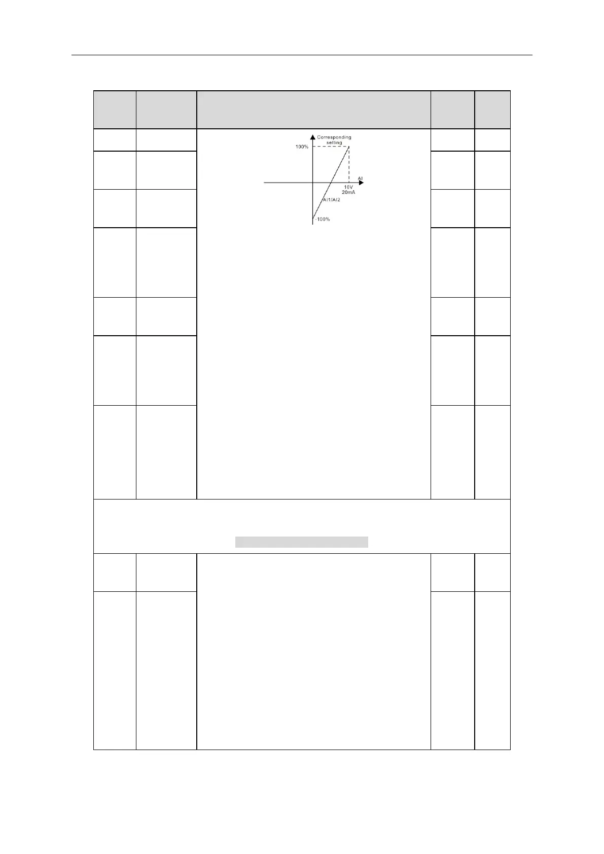
Note: AI2 can support 0~10V or 0~20mA input, when
AI2 selects 0~20mA input, the corresponding voltage of
20mA is 5V. AI3 can support the output of -10V~+10V.
The setting range of P05.32:0.00V~P05.34
The setting range of P05.33:-100.0%~100.0%
The setting range of P05.34:P05.32~10.00V
The setting range of P05.35:-100.0%~100.0%
The setting range of P05.36:0.000s~10.000s
The setting range of P05.37:0.00V~P05.39
The setting range of P05.38:-100.0%~100.0%
The setting range of P05.39:P05.37~10.00V
The setting range of P05.40:-100.0%~100.0%
The setting range of P05.41:0.000s~10.000s
1:On operation
2:Forward rotation operation
3:Reverse rotation operation
4: Jogging operation
5:The inverter fault
6:Frequency detection FDT1
7:Frequency detection FDT2
8:Frequency arrival
9:Zero speed running
10:Upper limit frequency arrival
11:Lower limit frequency arrival