I-Control manual page 20
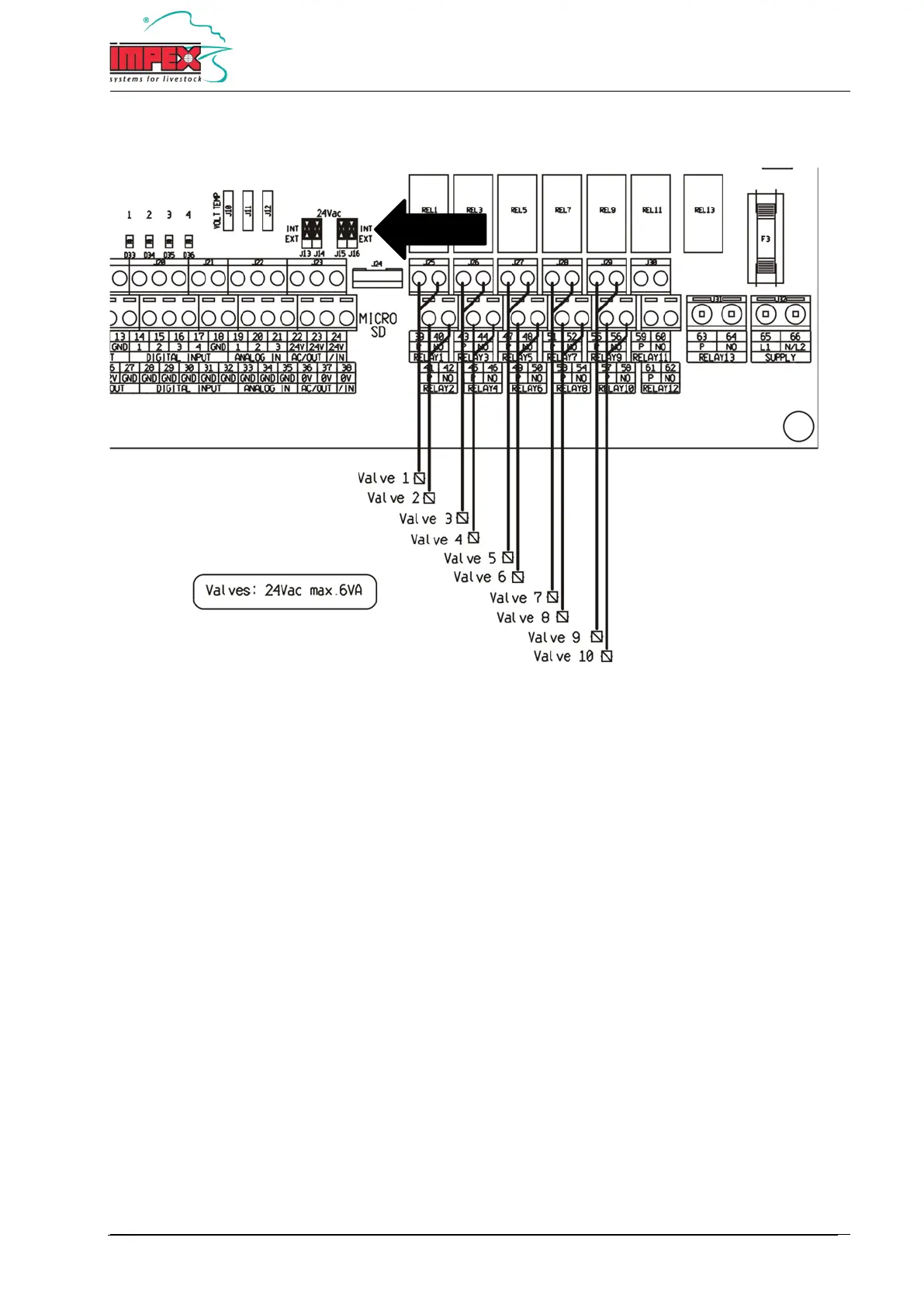
Flush valve connection diagram - 24V internal power supply
39 + 40 = Flush valve 1
41 + 42 = Flush valve 2
43 + 44 = Flush valve 3
45 + 46 = Flush valve 4
47 + 48 = Flush valve 5
49 + 50 = Flush valve 6
51 + 52 = Flush valve 7
53 + 54 = Flush valve 8
55 + 56 = Flush valve 9
57 + 58 = Flush valve 10
Note: The flush valves must be 24VAC with a maximal 6VA electric load.
Important: The 4 jumpers with the text '24VAC' must all be in 'INT' position. See diagram.
Note: The terminals 40, 42, 44, 46, 48, 50, 52, 54, 56 and 58 are galvanically connected. With a multi-cable, only
one terminal needs to be used.