I-Control manual page 21
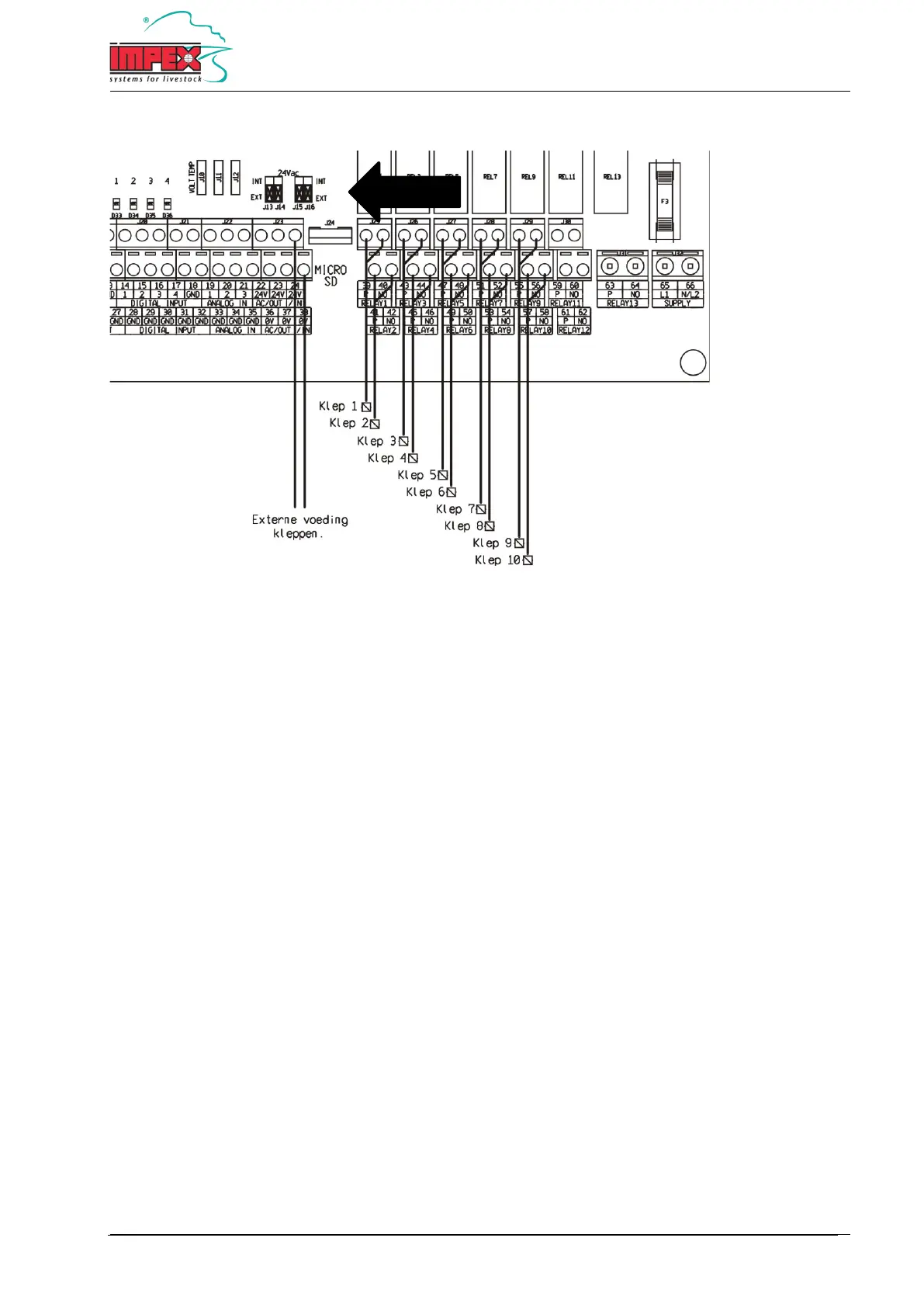
Flush valve connection diagram - External power supply
39 + 40 = Flush valve 1
41 + 42 = Flush valve 2
43 + 44 = Flush valve 3
45 + 46 = Flush valve 4
47 + 48 = Flush valve 5
49 + 50 = Flush valve 6
51 + 52 = Flush valve 7
53 + 54 = Flush valve 8
55 + 56 = Flush valve 9
57 + 58 = Flush valve 10
24 + 38 = External power input. Maximum 24VAC
Important: The 4 jumpers with the text '24VAC' must all be in 'EXT' position. See diagram.
Note: An external power supply may be needed if the internal power supply has insufficient power or if another
valve voltage other than 24VAC is desired.
Note: The maximum relay load for the valves is 24VAC/2Amp.
Note: The external power supply is not to exceed 24VAC.
Note: The voltage of the external power supply will also be present at terminals 22/23 and 36/37 and can
optionally provide power to a main valve.
Note: The terminals 40, 42, 44, 46, 48, 50, 52, 54, 56 en 58 are galvanically connected. With a multi-cable, only one
terminal needs to be used.