I-Control manual page 26
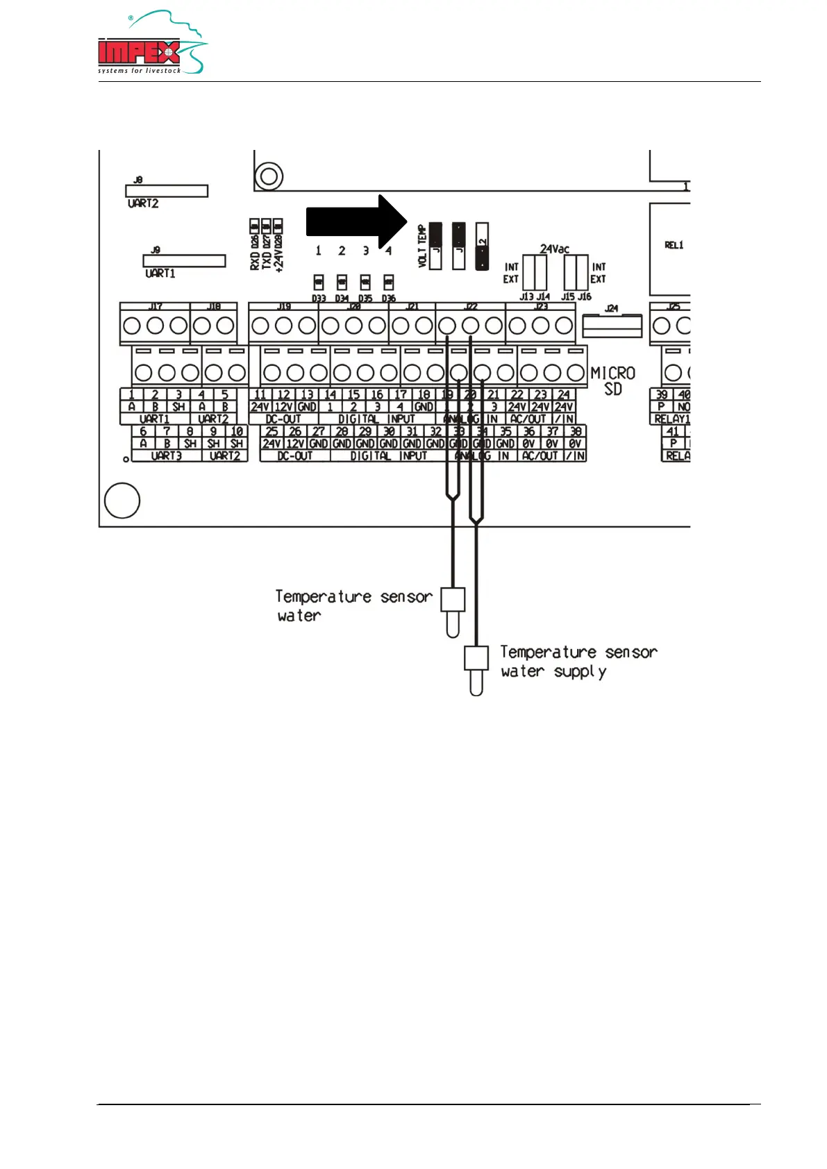
Temperature sensor connection diagram
19 + 33 = Drinking water circuit temperature sensor
33 = GND
20 + 34 = Water supply temperature sensor
34 = GND
Important: The corresponding jumpers must be in “TEMP” position. See diagram.
Note: Always use shielded cable with a minimum diameter of 0,8 mm² and connect the shield to the GND terminal.