I-Control manual page 29
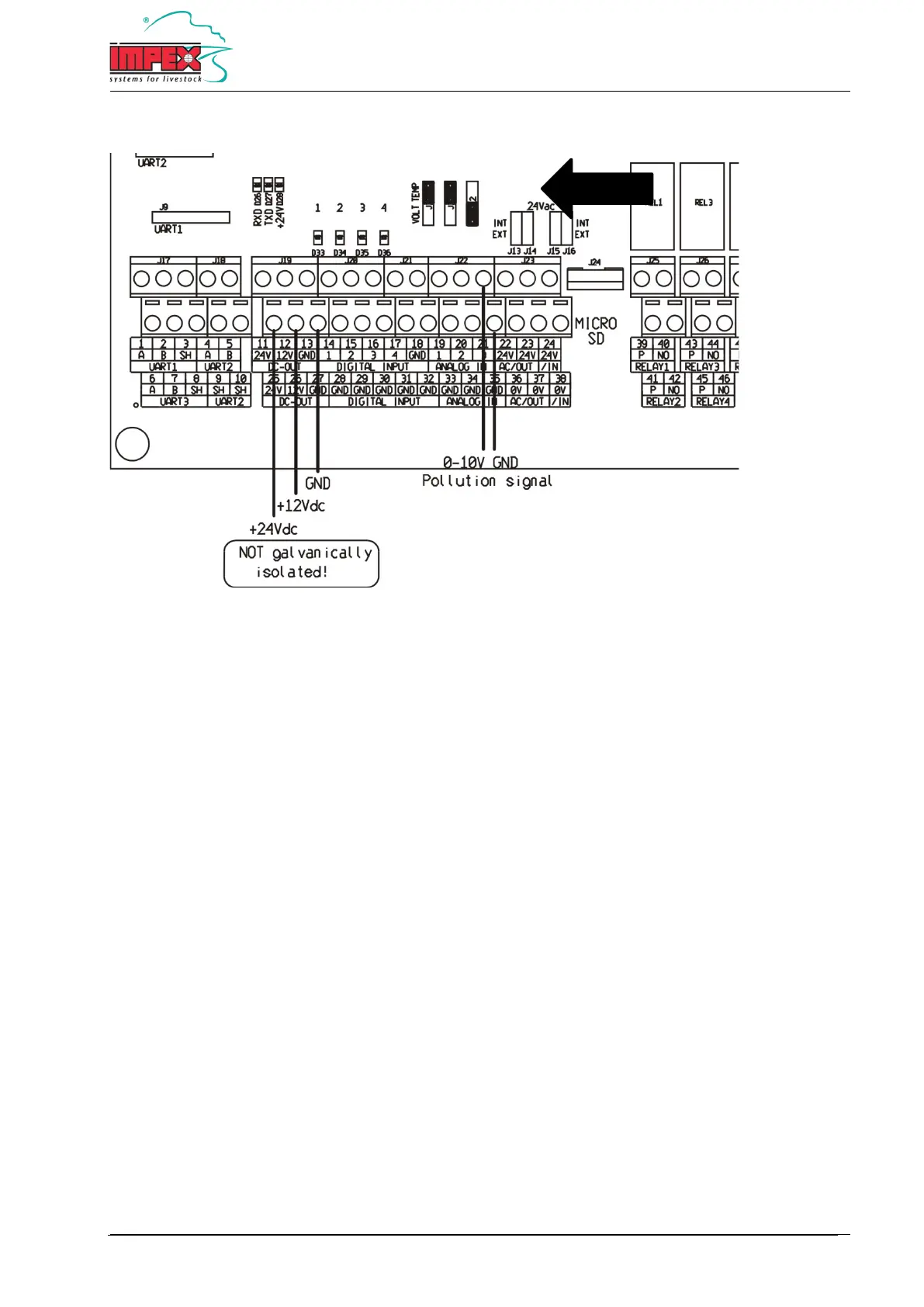
Analog dirty water sensor connection diagram
21 + 35 = 0-10V Input for dirty water sensor
21 = 0-10V input
35 = GND
11 + 25 = 24V DC power supply
Maximum 50 mA.
12 + 26 = 12V DC power supply
Maximum 50 mA.
13 + 27 = GND power supply
Important: The jumper of the 0-10V input must be in ‘VOLT’ position. See diagram.
Note: Always use shielded cable with a minimum diameter of 0,8 mm² for the dirty water sensor and connect the
shield to the GND terminal.
Note: The 12V or 24V power supply with a maximum of 50 mA can also be used to power a pollution sensor.
Note: The GND connection of the power supply is galvanically connected to all other GND connections, such as the
sensor inputs.