14
4 Lead Motor
4 lead motors are the least flexible but easiest to wire. Speed and torque will
depend on winding inductance. In setting the driver output current, multiply the
specified phase current by 1.4 to determine the peak output current.
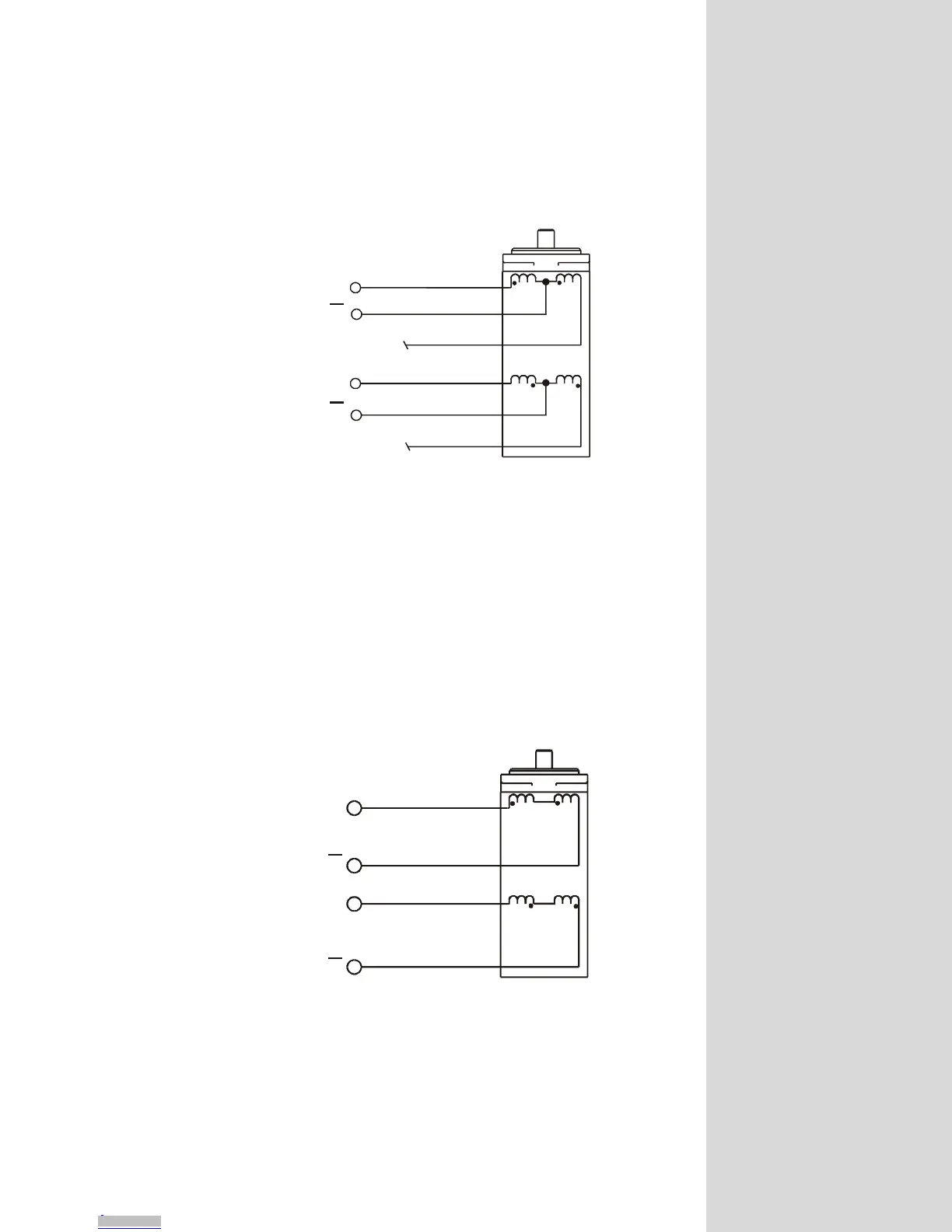
PHASE A
NO CONNECTION
NO CONNECTION
PHASE A
PHASE B
PHASE B
Figure 3.4: 6 Lead Motor, Half Coil Connection
Half Coil Configuration
As previously stated, the half coil configuration uses 50% of the motor
phase windings. This gives lower inductance, hence, lower torque output
at low speeds. As with the parallel connection of 8 lead motor, the
torque output will be increased at higher speeds. This configuration is
also referred to as half copper. In setting the driver output current,
multiply the specified per phase (or unipolar) current rating by 1.4 to
determine the peak output current.
PHASE A
PHASE A
PHASE B
PHASE B
Figure 3.5: 4 Lead Motor Connections
Downloaded from Arrow.com.Downloaded from Arrow.com.Downloaded from Arrow.com.Downloaded from Arrow.com.Downloaded from Arrow.com.Downloaded from Arrow.com.Downloaded from Arrow.com.Downloaded from Arrow.com.Downloaded from Arrow.com.Downloaded from Arrow.com.Downloaded from Arrow.com.Downloaded from Arrow.com.Downloaded from Arrow.com.Downloaded from Arrow.com.Downloaded from Arrow.com.Downloaded from Arrow.com.