32
In each case you can calculate the decimal equivalent by adding the weights of
the bits that are set in the I/O group.
Reading the state of inputs will work the very same way. In a real-world example
you may not be using LED’s, but rather outputing to, or receiving input from,
PLC inputs or outputs for process control applications. In this case, in your
MicroLYNX program, you may want to call up various subroutines when the
I/O group is at a certain state. This gives you the power of programming up to
63 events in your process controlled by the standard I/O group on the
MicroLYNX.
IO Variable Exercise #2
In this exercise we will use a short program that will use I/O group 20 as a
binary counter. The program will display the decimal equivalent of the binary
count on the screen. It will also move the motor a short distance and wait 0.25
seconds in between counts.
Type the following into the text editor window and save. Download to
MicroLYNX.
IOS 20 = 0,1,0 'set I/O group 20 = gen. purp. outputs, active low
IO 20 = 0 'set the state of I/O group 20 to 0
PGM 200 'start program at address 200
LBL IO_CNT 'name the program "IO_CNT"
VI=100000 'set the init. velocity = 100,000 munits/sec.
IO 20=IO 20+1 'add 1 to the value of I/O group 20
MOVR 10000 'move relative 10000 munits
HOLD 2 'suspend program until motion completes
DELAY 250 'wait 0.25 seconds
PRINT "\rThe decimal state of I/O Group 20 is: " IO 20;
BR IO_CNT, IO 20=<63 'loop to IO_CNT while I/O 20 is lss that 63
PRINT "\nALL DONE!" 'line feed to next line print ALL DONE
END
PGM
EXEC IO_CNT to run the program. The LED’s will cycle and the number will
count up on the terminal screen.
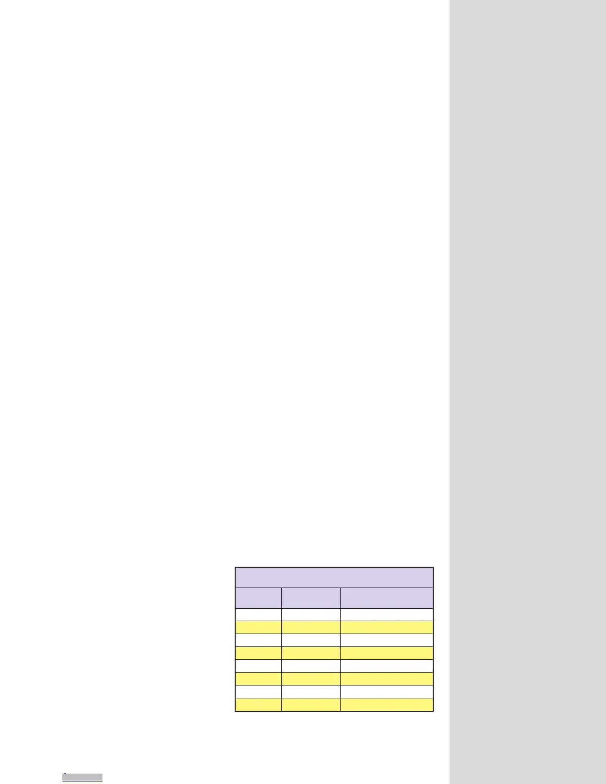
Setting the Digital Filtering for the I/O (IOF)
User-definable digital filtering
makes the MicroLYNX well
suited for noisy industrial
environments. The IOF variable
allows the user to software select
filter settings ranging from 215
Hz to 27.5 kHz.
The IOF variable has 1 param-
eter with a range of 1 to 7.
These are shown in table 8.2.
O/IdetalosIesopruPlareneGehtrofsgnitteSretliFFOI
)7-0=>mun<(>mun<=FOI
gnitteSretliF
ffotuC
ycneuqerF
esluPelbatceteDmuminiM
htdiW
0zHk5.72sdnocesorcim81
1 zHk7.31 sdnocesorcim63
2zHk98.6sdnocesorcim37
3 zHk44.3 sdnocesorcim541
4zHk27.1sdnocesorcim092
5 zH068 sdnocesorcim185
6zH034sdnocesillim261.1
)tluafed(7 zH512 sdnocesillim323.2
Table 8.2: IOF Settings
Downloaded from Arrow.com.Downloaded from Arrow.com.Downloaded from Arrow.com.Downloaded from Arrow.com.Downloaded from Arrow.com.Downloaded from Arrow.com.Downloaded from Arrow.com.Downloaded from Arrow.com.Downloaded from Arrow.com.Downloaded from Arrow.com.Downloaded from Arrow.com.Downloaded from Arrow.com.Downloaded from Arrow.com.Downloaded from Arrow.com.Downloaded from Arrow.com.Downloaded from Arrow.com.Downloaded from Arrow.com.Downloaded from Arrow.com.Downloaded from Arrow.com.Downloaded from Arrow.com.Downloaded from Arrow.com.Downloaded from Arrow.com.Downloaded from Arrow.com.Downloaded from Arrow.com.Downloaded from Arrow.com.Downloaded from Arrow.com.Downloaded from Arrow.com.Downloaded from Arrow.com.Downloaded from Arrow.com.Downloaded from Arrow.com.Downloaded from Arrow.com.Downloaded from Arrow.com.Downloaded from Arrow.com.Downloaded from Arrow.com.