6
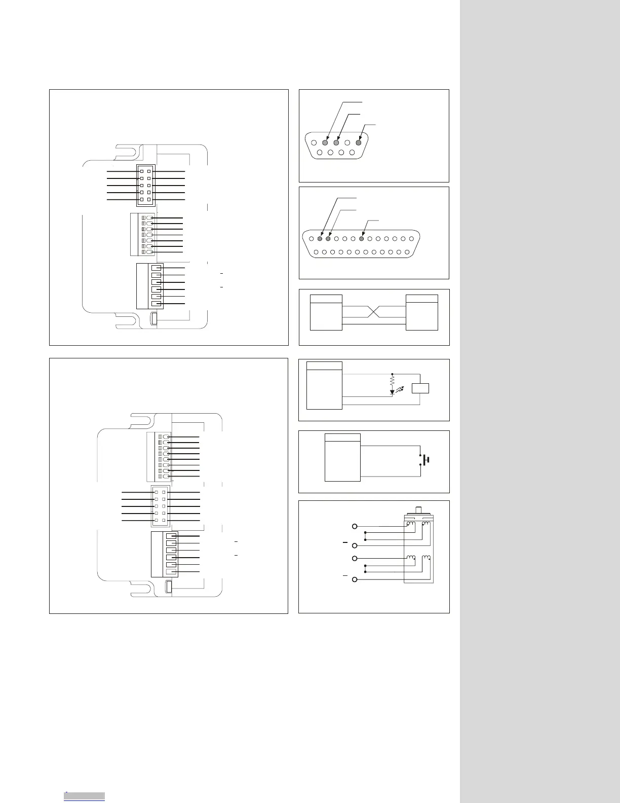
Figure 1.3: Connector Pin Configuration
Connector Information
MOTOR PHASE A
MOTOR PHASE B
MOTOR PHASE A
MOTOR PHASE B
POWER SUPPLY INPUT (+V)
POWER SUPPLY RETURN (GND)
N.C.: PIN 1
PIN 2: RS-232 RX
PIN 1: V PULLUP
PIN 2: I/O LINE 21
PIN 3: I/O LINE 22
PIN 4: I/O LINE 23
PIN 5: I/O LINE 24
PIN 6: I/O LINE 25
PIN 7: I/O LINE 26
RS-232 TX: PIN 3
PIN 4: N.C.
Communications Ground: PIN 5 PIN 6: RS-485 RX+
RS-485 RX-: PIN 7
PIN 8: RS-485 TX-
RS-485 TX+: PIN 9
PIN 10: Communications Ground
PIN 8: I/O Ground (Isolated)
MicroLYNX Connections
Communications: 10 Pin Header
I/O: 8 Position Phoenix
MOTOR PHASE A
MOTOR PHASE B
MOTOR PHASE A
MOTOR PHASE B
POWER SUPPLY INPUT (+V)
POWER SUPPLY RETURN (GND)
N.C.: PIN 1
PIN 2: I/O LINE 21
I/O LINE 22: PIN 3
PIN 4: V PULLUP
I/O LINE 23: PIN 5
PIN 6: Out of Limit -
I/O LINE 24-: PIN 7
PIN 8: Out of Limit +
I/O LINE 25: PIN 9
PIN 10: I/O Ground (Isolated)
PIN 1: RS-232 RX
PIN 2: RS-232 TX
PIN 3: RS-485 RX -
PIN 4: RS-485 RX+
PIN 5: RS-485 TX -
PIN 6: Communications Ground
PIN 7: RS-485 TX+
MicroLYNX Connections
Communications: 7 Position Phoenix
I/O: 10 Pin Header
11323456 87 9 10 11 12
14 15 16 17 18 19 20 21 22 23 24 25
PIN 3: RS-232 Receive Data (RX)
PIN 2: RS-232 Transmit Data (TX)
PIN 7: Communications Ground
25 Pin Serial COM Port
1
6789
2345
PIN 2: RS-232 Receive Data (RX)
PIN 3: RS-232 Transmit Data (TX)
PIN 5: Communications Ground
9 Pin Serial COM Port
RS-232 Communications Connections
RX
TX
CGND
TX
RX
V PULLUP
CGND
IO 2
x
IO 2
x
IO GND
IO GND
MicroLYNX
MicroLYNX I/O
MicroLYNX I/O
Ter mi na l/P C
CURRENT
LIMITING
RESISTOR
LED
Out
ut To LED
Input Controlled By A Switch
8 Lead Motor - Series Connection
+5 to +24VD C
+
Normally
Open Switch
PHASE A
PHASE A
PHASE B
PHASE B
Downloaded from Arrow.com.Downloaded from Arrow.com.Downloaded from Arrow.com.Downloaded from Arrow.com.Downloaded from Arrow.com.Downloaded from Arrow.com.Downloaded from Arrow.com.Downloaded from Arrow.com.