16
1 2 3 4 5 6 7 8 9 10 11 12 13
14 15 16 17 18 19 20 2 1 22 23 24 25
25 Pin Serial Port
on Host PC
9 Pin Serial Port
on Host PC
1 2 3 4 5
6 7 8 9
Host PC
MICRO
TM
4
MicroLYNX-4 (10 Pin Header)
123
RX
TX
CGND
MicroLYNX-4 (7 Pin Terminal Block)
PIN 1
RX
RXTX
TX
CGND CGND
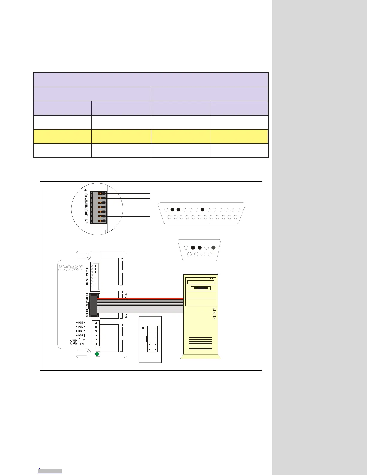
Figure 4.2: RS-232 Interface Connection
noitcennoCXNYLorciM232-SR
XNYLorciM CP
redaeHniP01 xineohPniP7 troPlaireSniP52 troPlaireSniP9
)XR(ataDevieceR3niP)XR(ataDevieceR1niP)XT(ataDtimsnarT2niP)XT(ataDtimsnarT3niP
)XT(ataDtimsnarT2niP )XT(ataDtimsnarT2niP )XR(ataDevieceR3niP )XR(ataDevieceR2niP
DNGC5niPDNGC6niPDNGC7niPDNGC5niP
Table 4.1: RS-232 Interface Connection
When using the RS-232 interface the MicroLYNX must be within 50 feet of the
communications host.
RS-485 Interface
In a system consisting of a single MicroLYNX, the RS-485 interface should be used
if the MicroLYNX will be more than 50 feet from the host PC. Since most PC’s do
not come with an RS-485 interface preinstalled, you will have to install an RS-485
MX-CC100-000
COMMUNICATIONS
PIN 1
PIN 2
PIN 9
PIN 10
Downloaded from Arrow.com.Downloaded from Arrow.com.Downloaded from Arrow.com.Downloaded from Arrow.com.Downloaded from Arrow.com.Downloaded from Arrow.com.Downloaded from Arrow.com.Downloaded from Arrow.com.Downloaded from Arrow.com.Downloaded from Arrow.com.Downloaded from Arrow.com.Downloaded from Arrow.com.Downloaded from Arrow.com.Downloaded from Arrow.com.Downloaded from Arrow.com.Downloaded from Arrow.com.Downloaded from Arrow.com.Downloaded from Arrow.com.