VGC
TM
SEQUENTIAL VALVE GATE CONTROL
INSTRUCTION MANUAL
©INCOE® CORPORATION 2/2009
Pg.
www.incoe.com
OPERATION
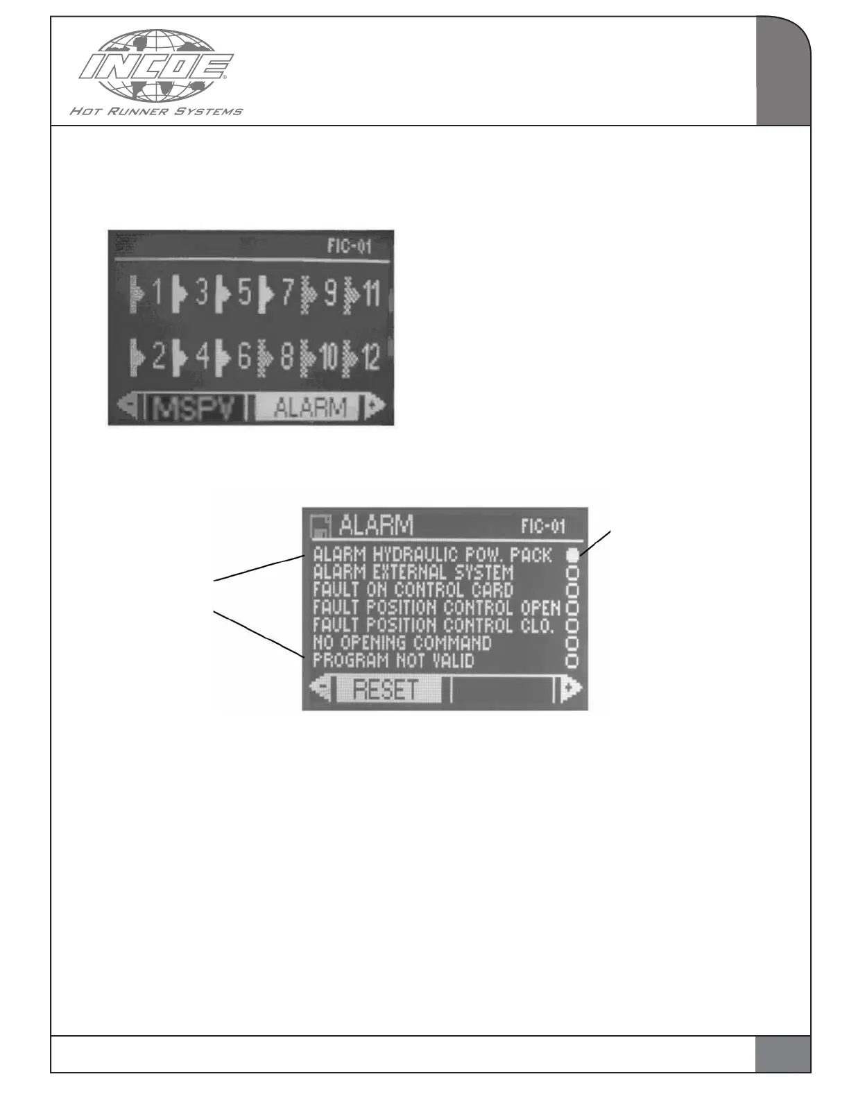
2.6 MANAGEMENT OF ALARMS
Select and validate the function ALARM from the
main page.
The page hereunder is displayed :
Alarm hydraulic power pack : shows the absence
of the external power pack or of the shunt between
pins 1 and 6 inside the B connector on the backside
of the controller
Alarm external system : alarm contact coming
from whatever device around the sequential
control cabinet.
Faulty control card : shows that a control card for
actuating outputs is faulty.
Fault position control open (valid if option position
control is present) : shows that the limit switch did
not confirm the actual pin on opening.
Fault position control close (valid if option po-
sition control is present) : shows that the limit
switch did not confirm the actual pin on closing.
No opening command : shows that no valve gate
was programmed to open in the injection cycle. If
so the injection cycle is stopped.
Program not valid : shows an error in program-
ming (not corresponding to screw calibration for
instance, etc…).
This page shows the current alarms.
RESET : to reset both alarm contacts for injection
safety.
Press ESC to go back to main page.
Various types
of alarms
The LED shows that the
corresponding alarm is
active
2
15