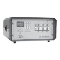
VGC
TM
SEQUENTIAL VALVE GATE CONTROL
INSTRUCTION MANUAL
©INCOE® CORPORATION 2/2009
Pg.
www.incoe.com
1
5
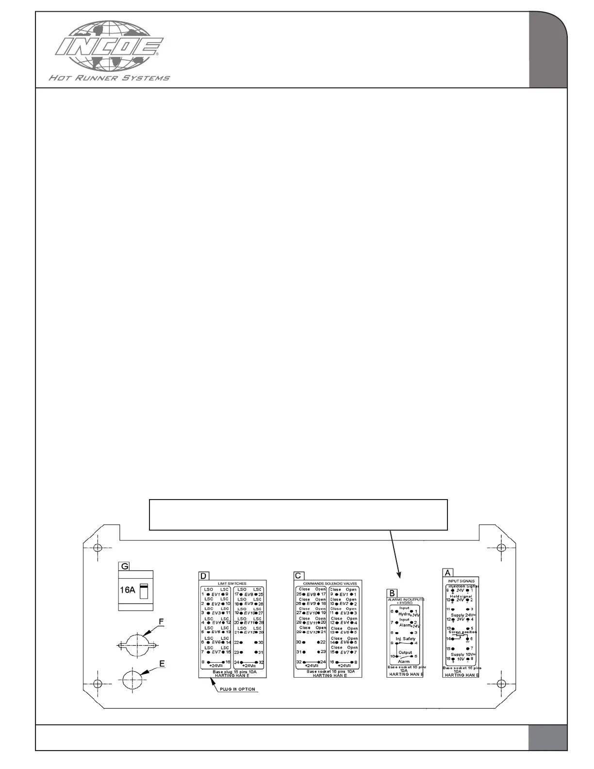
1.6 CONNECTIONS FOR VGC SEQUENTIAL
VALVE GATE CONTROL CABINET
A: Connector for input signals (16 pins 10A female).
B: Connector for alarm inputs and outputs, as well
as for security on hydraulic power pack (10 pins
10A female).
C: Connector for commands to valve gates,
voltage 24V DC, 1.5 Amps per valve gate
(32 pins 10A female).
D: Option : Connector for limit switches on valve
gates (32 pins 10A male).
E: Power supply cable inlet 3G2,5mm2 (Supply
voltage 230V AC 50/60Hz).
F: Fuse holder with fuse 16A on cabinet.
G: Circuit breaker 16A (switching cabinet on / off).
IMPORTANT NOTICE:
When connecting the signals from the press to
connector A on cabinet, it is recommended to split
0-10V signals and 0-24V signals. Use a cable with
shielded pairs, connect screw position with the
first pair and hold signal, injection signal and 0-24V
supply with the other pairs.
1.7 DIMENSIONS IN. (MM)
• Cabinet VGC Seq Valve Gate Control for 12
valve gates :
17” (431mm) L x H 8.5” (216mm) H x 18.5”
(470mm) D
1.8 FUSES AND CIRCUIT BREAKERS
• Fuse 16A type gI for cabinet (size 10x38 mm).
• Circuit breaker 16A.
• Fuses 6.3A on each control card (size 5x20 mm).
1.9 APPLICABLE STANDARDS
Cabinet VGC Sequential Valve Gate Control is
approved for the Specification CE 73/23 “Low
voltage” and fullfill the EN 61010-1 standards.
They also comply with the following standards:
Electrical noise industriel environnent : EN 50081-2
Electrical Noise Immunity in industrial
environment: EN50082-2
INTRODUCTION
There MUST be a plug on connector B. Use either a dummy plug,
or a plug that is using the features intended for Connector B.