VGC
TM
SEQUENTIAL VALVE GATE CONTROL
INSTRUCTION MANUAL
©INCOE® CORPORATION 2/2009
Pg.
www.incoe.com
2.0 STARTING UP
Plant power 230V AC 50/60 Hz Single Phases cable
supplied.
Make sure that all connections to the backside
of the cabinet are correct (command signal,
alarms….). Switch the cabinet on with the 16A
circuit breaker.
The following pages appear after 5 seconds :
Important Notice: When the cabinet VGC Seq Valve
Gate Control is not in service, the A connector on
the backside of the cabinet must be disconnected
in order not to interfere with the signals from the
injection machine.
2.1 CALIBRATION
For proper use of the controller with the injection
molding machine, it is required to calibrate the
screw travel first.
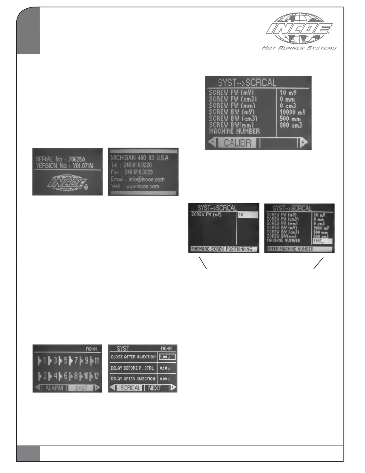
To access the calibration page, simply select the
SYST function on white background, validate and
then select the SCRCAL function.
Select SCRCAL to calibrate the screw travel.
The following page is displayed.
Validate the function CALIBR to enter the calibration
process from this page and enter the calibration
values one after the other by moving the screw on
the injection machine.From this point, the process
must be brought to the end.
Guiding messages for the operator
Notice: The machine number is important information
to enter and to confirm which machine the calibration
process has been done on the controller.
Please note that if this controller is moved to another
machine, it must be recalibrated if you wish to use
the screw position signal for programming.
All words preceded by “MES.“ are values read
from the injection machine.
All words preceded by “VAL. “ are inputs made by
the operator.
OPERATION
2
8