Leak Detection Sensors Page 17 - 1
17
Internally, the TS-1001/504 has 12 and the
TS-2001/508 has 24 IS (intrinsically safe) leak
detection sensor input channels. Optionally —
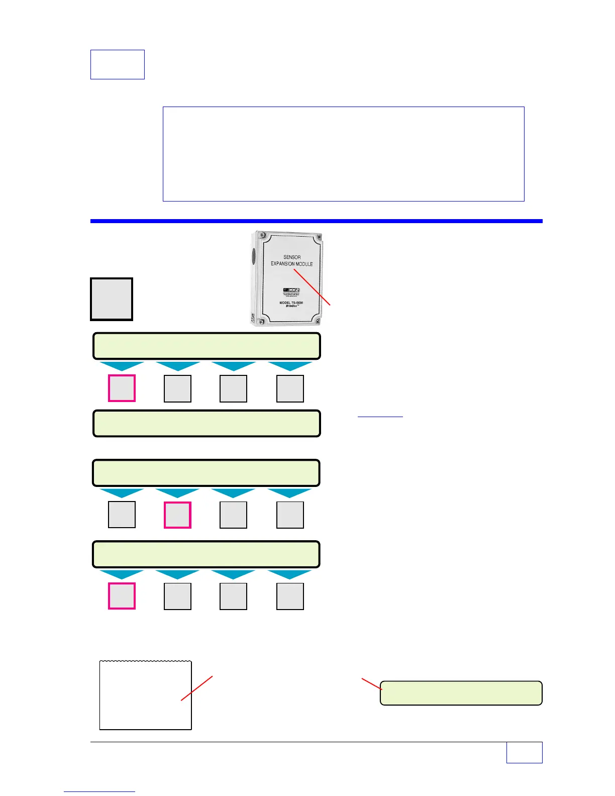
with the addition of 1 or 2
external
TS-SEM Sensor
Expansion Module(s) — the total number of sensors
can be increased to 28 for the TS-1001/504 or to
40 for the TS-2001/508.
This menu will appear only when the No. of
Sensors is greater than zero (as defined in
the system setup menu).
The installer must
document the type, the location, and the
input sensor channel of each leak-detection
sensor.
Sensor alarms can be setup to print, or send alarm
reports, and to energize output groups that can be
programmed to activate annunciator warning horns,
indicator lights, relays, or various other external
devices.
Fill-in the Worksheets that are provided in this
chapter with Output Group assignments for each
sensor. Use the Table of Contents (TOC) to locate
and compare with other Output Group Worksheets.
17 Sensors (Leak Detection)
SETUP PROGRAMMING
Sensors Menu
H U
Press this key
MENU
× and follow the
7
highlighted
sequence below
SELECT MENU OPTION
SETUP
UPGRADE LANGUAGE DATALOG
M1 M2 M3 M4
Press
DOWN
▼ key two or three times...
SETUP MENU (MORE)
EXIT SYSTEM TANKS PROBES
SENSORS (MORE)
AUTO CFG SENSOR 1 SENSOR 2 SENSOR 3
M1 M2 M3 M4
SETUP MENU (MORE)
TS-ROM
SENSORS
AUX INPUT IO MODULE
M1 M2 M3 M4
NOTE
☞
SENSOR ALARMS ACTIVE 1-1-1998
WATER T1 DIS 3 11:35:02PM
ALARM REPORT
1/1/1998 11:35 PM
WATER PRESENT
T1 DIS 3
SENSOR NO. 3
Contents:
Sensors Menu
Naming Sensors
Standard Sensors (ID)
BriteSensor (ID)
Output Groups Assignments
Worksheets 17-1 & 17-5
See the Table of Contents to find topics in
this manual. See the Preface for general
information about this manual. And see the
Installation, Operator’s, TroubleShooting
Guides, and Application Notes for other
reference material.
Naming Sensors
Sensors can be renamed to help
identify the location and type on
Reports and Displayed Alarms.
For example: a TSP-DIS sensor
is installed at Tank 1, to sensor
channel 3. It was renamed
from
-
SENSOR 3
to -
T1 DIS 3.
 Loading...