20
tina46e1-b (2017-12) BPG402.om
TxD
RxD
Degas
42 k
Ω
4
1
11
9
13
14
7
8
2
12
5
15
1.25 AT
24V
Degas
Ident.
RS232
10
-
-
-
Measuring
signal
V
S
6
SP A
SP B
SP A
SP B
3
6
1)
( )
-
Threshold value
8
9
1
15
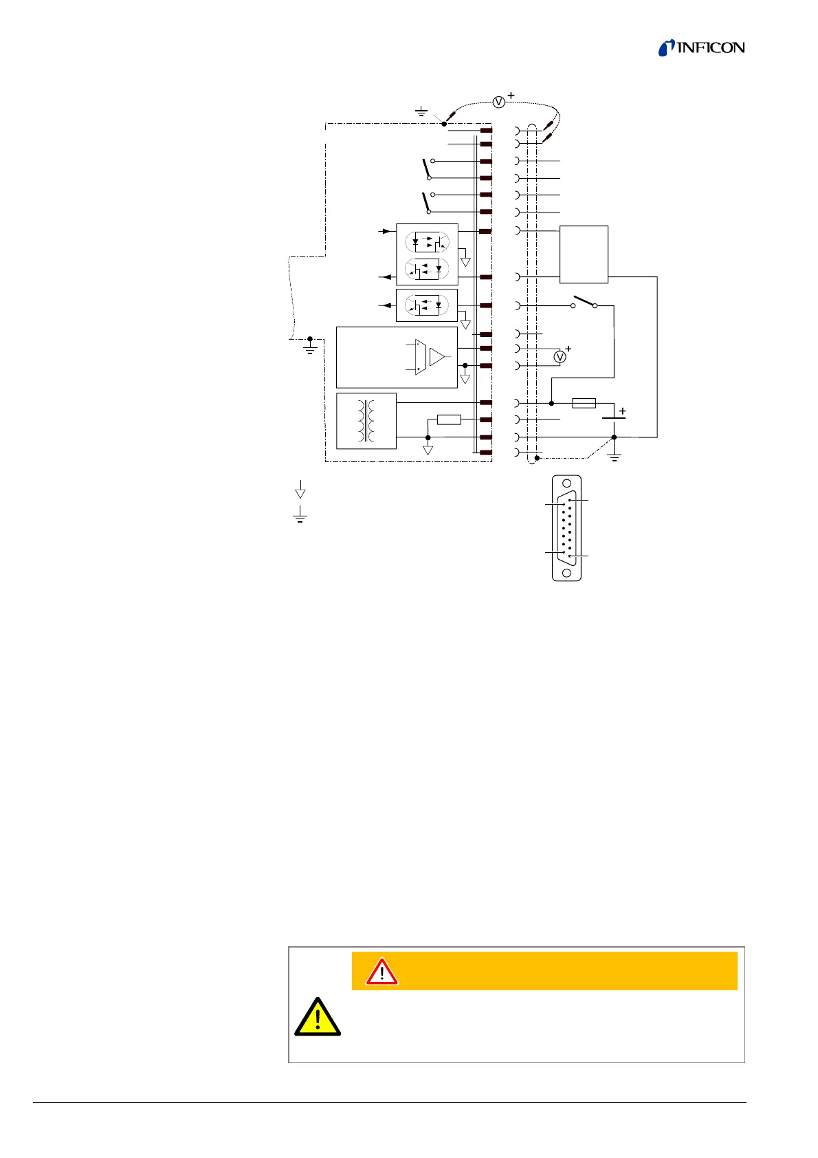
D-Sub,15-pin,
female,
soldering side
Common (power GND 24V supply)
Ground (housing, vacuum connection)
Electrical connection
Pin 1 Relay switching function A, common contact
Pin 2 Measuring signal output 0 … +10 V
Pin 3 Threshold (setpoint) A
1)
0 … +10 V
Pin 4 Relay switching function A, NO contact
Pin 5 Supply common 0 V
Pin 6 Threshold (setpoint) B
1)
0 … +10 V
Pin 7 Degas (active high) 0 V/+24 V
Pin 8 Supply (V
s
) +24 V
Pin 9 Relay switching function B, common contact
Pin 10 Gauge identification
Pin 11 Relay switching function B, NO contact
Pin 12 Measuring signal common
Pin 13 RS232C, TxD
Pin 14 RS232C, RxD
Pin 15 Do not connect
1)
Do not connect pin 3 and pin 6 for normal operation of the gauge. These pins
are reserved for adjustment of the setpoint potentiometers (→ 40).
WARNING
The supply common (Pin 5) and the shielding must be connected at
the supply unit with protective ground.
Incorrect connection, incorrect polarity or inadmissible supply voltages
can damage the gauge.
Sensor cable connection
BPG402-SD, -SE, -SP