tina46e1-b (2017-12) BPG402.om 23
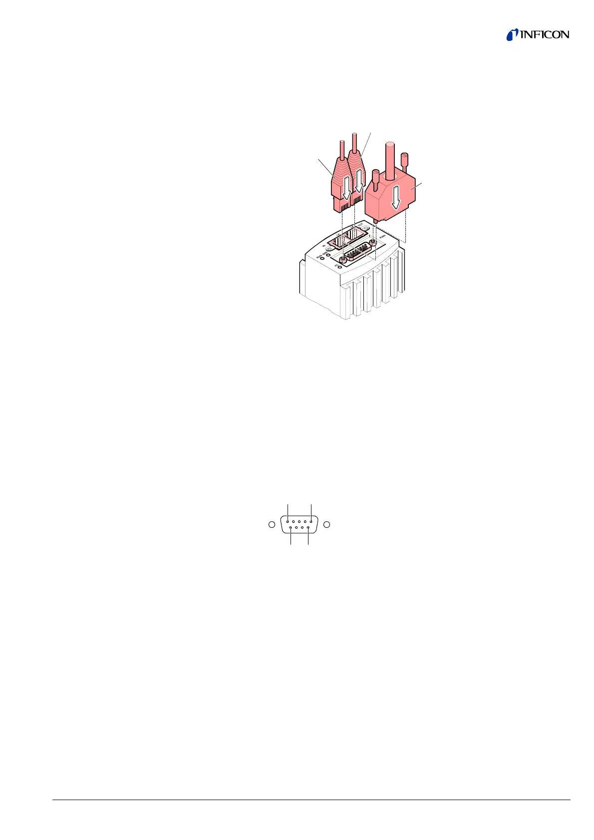
Connect the Ethernet cables (and sensor cable) to the gauge: From the
previous device the cable connected to the <OUT> port has to be con-
nected to the BPG402-SE <IN> port. And the cable from the BPG402-SE
<OUT> port has to be connected to the next device's <IN> port.
Sensor cable
FCC68 cable
<IN> port
FCC68 cable
<OUT> port
Secure the sensor cable connector using the lock screws.
For operating BPG402-SP via Profibus, an interface cable conforming to the
Profibus standard is required.
If no such cable is available, make one according to the following indications.
Only a cable that is suited to Profibus operation may be used (→ [6], [12]).
Make the Profibus interface cable according to the following indications:
1 5
6 9
D-Sub, 9-pin
male, soldering side
Pin 1 Do not connect
Pin 2 Do not connect
Pin 3 RxD/TxD-P
Pin 4 CNTR-P
1)
Pin 5 DGND
2)
Pin 6 VP
2)
Pin 7 Do not connect
Pin 8 RxD/TxD-N
Pin 9 Do not connect
1)
Only to be connected if an optical link module is used.
2)
Only required as line termination for devices at both ends of bus system
(→ [6]).
3.2.2.4 Making a Profibus
Interface Cable
(BPG402-SP)
Cable type
Procedure