Do you have a question about the Inficon UL1000 Fab and is the answer not in the manual?
Defines safety symbols like Caution, Warning, Danger, and Skilled personnel for operational safety.
Explains indicators, notices, and tips for using the handbook.
Illustrates common vacuum symbols used in the manual.
Defines key technical terms like Autoranging and Autotune.
Lists global INFICON service center contact details for immediate assistance.
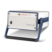
Explains the primary functions and applications of the leak detectors.
Lists physical characteristics and operating limits of the leak detector.
Details the electrical specifications, power requirements, and protection types.
Lists additional specifications and operating environment requirements.
Instructions for safely unpacking the leak detector and checking contents.
Lists all items included with the leak detector.
Safe methods for moving and securing the UL1000/UL1000 Fab unit.
Guidelines for selecting a suitable operating environment for the instrument.
Guidance on connecting to power and safety precautions.
Explains how to connect external data acquisition devices.
Details the functions and pin assignments of the digital output relays.
Explains the function and pin assignments of the digital input terminals.
Describes how the recorder output signals are provided and their characteristics.
Details serial communication and remote control connectivity options.
Explains the inlet, exhaust, and vent port configurations.
Lists the factory default settings for various functions.
Step-by-step instructions for powering on, connecting, and performing first measurements.
Procedure for performing an internal calibration to ensure accuracy.
Steps to verify the measurement accuracy after calibration.
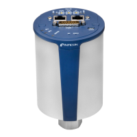
Overview of the device's main physical components and housing.
Explains the vacuum system diagram and the function of its components.
Details on the LC Display, buttons, and soft keys for user interaction.
Explains the specific functions of the LC Display, START, STOP, and ZERO buttons.
How to navigate menus using the MENU button and soft keys.
Instructions for entering numerical values and making selections.
Explains the procedures and diagrams for the Vacuum mode.
How to use the leak detector in Sniffer mode.
Explains the automated testing process using the TC1000 chamber.
General information about the display's use for signals and menu navigation.
What is shown on the display during the device's startup sequence.
How measurement data is displayed in numerical and trend modes.
How to adjust the loudness of the speaker and understand volume levels.
Interpretation of the status icons shown in the display's bottom line.
How leak rates are shown digitally with bar graphs and input pressure.
How leak rates are displayed graphically over time with digital readings.
Overview of the main menu and its 7 sub-menus.
Settings related to display appearance like scale, contrast, and axis.
Adjusting bargraph and trend mode scales to linear or logarithmic.
Configuring the display range for leak rates automatically or manually.
Setting the length of the time axis in trend mode.
How to adjust the display contrast for better readability.
Option to display internal background leak rate in standby mode.
Setting the number of decimal places for displayed leak rate values.
Parameter defining the lower leak rate limit in vacuum modes.
Interface for selecting between Vacuum, Sniff, and Auto Leak Test modes.
Definition and effect of the first trigger level threshold.
Definition and effect of the second trigger level threshold.
Adjusting minimum and regular speaker volume levels.
Choosing preferred units for leak rate and pressure measurements.
Setting a delay for alarms after pressing START.
Choosing between Pinpoint, Leak Rate Prop., Setpoint, and Trigger Alarm types.
How to start calibration from different modes.
Details on automatic and manual internal calibration processes.
Step-by-step guide for performing external calibration.
General guidance on interpreting and handling error/warning messages.
Detailed list of error codes, their messages, and possible solutions for troubleshooting.
Overview of service levels, safety, and general maintenance principles.
Procedures for returning equipment for repair or maintenance.
Explanation of the symbols and codes used in the maintenance plan.
Table detailing maintenance tasks, intervals, and required parts.
Specific tasks for the 1500-hour service interval.
Tasks and recommendations for the 4000-hour service interval.
Procedures required for the 8000-hour service interval.
Tasks for the 16000-hour service interval, related to pump life expectancy.
Specific notes regarding the maintenance of the SplitFlow 80 pump.
General description of non-routine maintenance tasks.
Step-by-step guide on how to open the instrument covers for maintenance.
Instructions for inspecting and replacing the air filter inserts.
Steps for removing and installing the exhaust silencer.
Procedures for checking, emptying, and replacing the exhaust filter.
How to check and add oil to the D16B pump.
Detailed steps for changing the oil in the D16B backing pump.
Information on maintenance intervals for the scroll pump.
A diagram illustrating the characteristic curve of the TPR265 sensor.
| Type | Helium Leak Detector |
|---|---|
| Measurement Principle | Mass Spectrometry |
| Minimum Detectable Leak Rate (Helium) | 5 x 10^-12 mbar l/s |
| Response Time | <1 second |
| Operating Temperature | 10°C to 40°C |
| Power Supply | 100-240 V AC, 50/60 Hz |
| Mobility | Portable |
| Application | Semiconductor manufacturing, vacuum systems, and other high-sensitivity leak detection applications |
| Test Port | KF25 |
| Interface | RS-232, Ethernet |
| Leak Detection Range | 5 x 10^-12 to 10^-2 mbar l/s |