40
tina46e1-b (2017-12) BPG402.om
The threshold values of the switching functions are set locally on the potentiome-
ters of the gauge that are accessible via the openings on one side of the gauge
housing.
• Voltmeter
• Ohmmeter or continuity checker
• Screwdriver, max. ø2.5 mm
The procedure for setting thresholds is identical for all switching functions.
Put the gauge into operation.
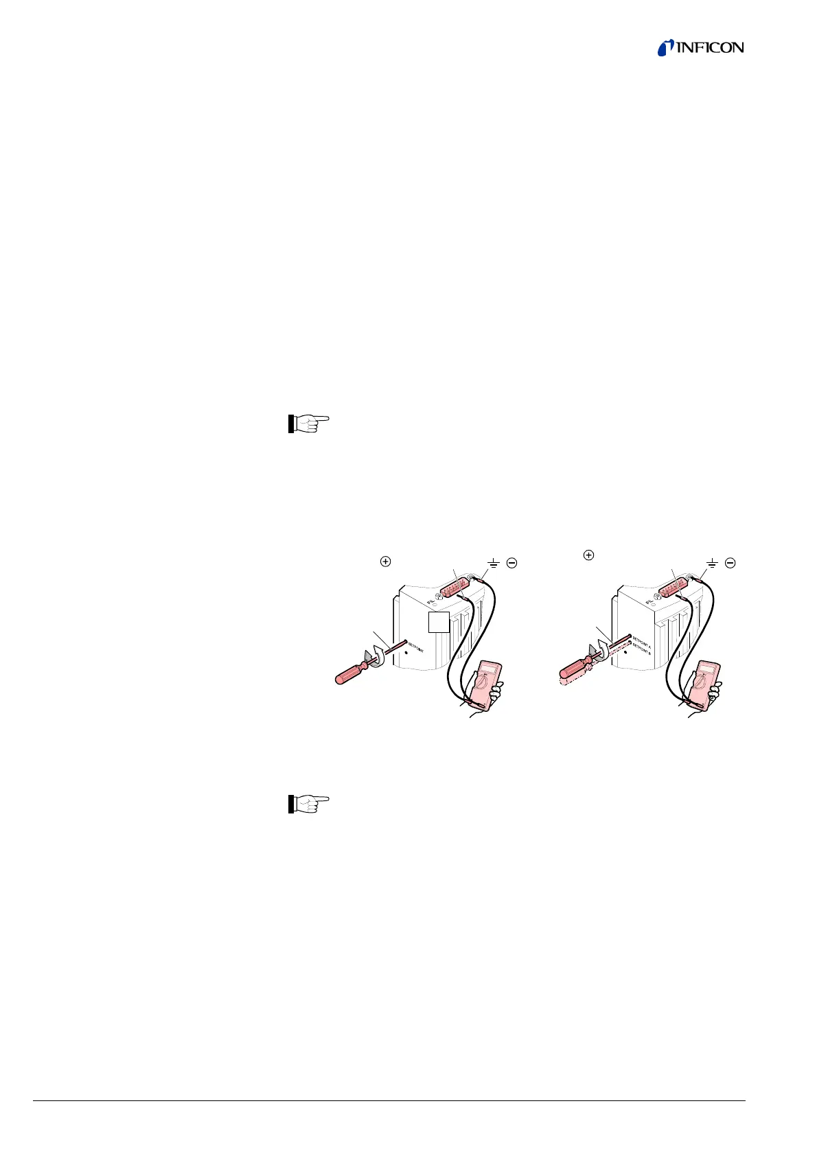
Connect the + lead of a voltmeter to the threshold measurement point of the
respective switching function (Pin 3 or Pin 6).
Connect the – lead of the voltmeter to a ground contact nearby (e.g. locking
screw of the connector, vacuum flange or housing of the gauge).
The threshold voltages are referenced to ground (housing, vacuum
connection), not to Pin 5 (common power GND 24
V supply).
BPG402-S
BPG402-SL
BPG402-SD
BPG402-SE
BPG402-SP
max. ø2.5
( )
Setpoint Pin 3
max. ø2.5
( )
Setpoint
A
Pin 3
Setpoint
B
Pin 6
Using a screwdriver (max. ø2.5 mm), set the voltage of the selected
switching function to the desired value U
Threshold
.
There is no local visual indication of the status of the switching functions.
However, a functional check of the switching functions (On/Off) can be
made with one of the following methods:
• Reading the status via fieldbus interface, for BPG402-SD → [1],
for BPG402-SE→ [3], for BPG402-SP → [2].
• Measurement of the relay contacts at the sensor cable connector
with an ohmmeter / continuity checker (→ 19, 20).
4.13.1 Setting the Switching
Functions
Required tools
Procedure