4 | Installation INFICON
4.2.2
|
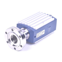
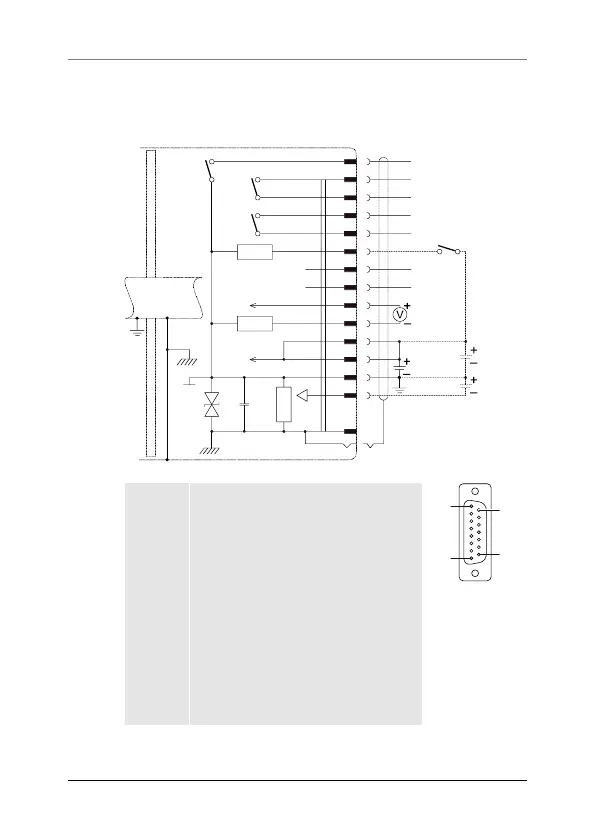
D-sub, 15-pin Connector
If no sensor cable is available, make one according to the follow-
ing diagram. Connect the sensor cable.
4
1
8
9
10
13
14
2
12
7
11
5
15
6
3
10
W
SP1
SP2
Ident
18 V
680 nF
1 M
case
15 V
15 V
Remote
Zero Adjust
Status
14...30 V
TxD
RxD
Pin 1, 4 Relay SP1, closing contact
D-sub, 15-pin
female
soldering side
1
8
9
15
Pin 2 Signal output (measurement signal)
or thresholds SP1/2
Pin 3 Status
Pin 5 Supply common
Pin 6 Supply (-15V)
Pin 7, 11 Supply (+14…+30V or +15V)
Pin 8, 9 Relay SP2, closing contact
Pin 10 Gauge identification or Remote Zero
Adjust
Pin 12 Signal common
Pin 13 RS232, TxD
Pin 14 RS232, RxD
Pin 15 Housing (Chassis Ground)
case Connector case
22 tina52e1-h (2024-09)