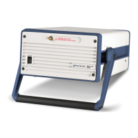
14 tinb07e1-e 2011-07 Vacuum Gauge Controller
3.3.6 CONTROL
The CONTROL connection (Fig. 3-4, 11, Pos. D) con-
tains the following signal pins:
• Analog outputs for the signals of the individual chan-
nels
• Recorder output. This is a programmable analog out-
put which can be assigned to one of the three chan-
nels.
• HV-EMI. Used to switch the high-vacuum circuit of the
PEG sensor on and off. The signal levels are: On =
+24 V. Off = 0 V. See Reference [7].
Pin assignment
Fig. 3-9 CONTROL appliance plug (D-Sub, 9-pin)
1 Connect the peripheral components with the CON-
TROL connection. Use a shielded connection
cable.
NOTE:
The analog outputs (pins 1, 2, 6) differ from the dis-
played values by no more than ±50 mV.
3.3.7 RS232C
The RS232C serial interface (Fig. 3-4, 11, Pos. F)
allows remote control of the unit via a computer or a ter-
minal. See Chapter 6 Computer interface, 32.
In addition, the interface may be used for firmware
updates. See Chapter 7.2 Program transfer mode, 45.
Pin assignment
Fig. 3-10 RS232C appliance socket (D-Sub, 9-pin)
1 Connect the serial interface of the computer with
the RS232C connection. Use a shielded cable.
NOTE:
Use a serial extension cable with a 9-pin plug and a
9-pin socket. The cable must not contain any crossed
wires.
1 Analog output 1
2 Analog output 3
3GND
4 HV-EMI 3
5 HV-EMI 1
6 Analog output 2
7 Recorder output
8GND
9 HV-EMI 2
1 n.c. / SUP
2TXD
3RXD
4n.c.
5GND
6DSR
7n.c.
8CTS
9GND
Artisan Technology Group - Quality Instrumentation ... Guaranteed | (888) 88-SOURCE | www.artisantg.com

 Loading...