5.0 ISC TROUBLE SHOOTING
CHART
TROUBLE CAUSE AND/OR DISPLAY WHAT TO DO
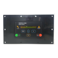
ISC POWER light is off. No message in display, no lights on. 1. Check fuse and wiring connections.
2. Check power source disconnect box.
Bad system air pressure readings. “SENSOR FAILURE” 1. Check for defective ISC air system
pressure transducer, bad connections
or broken wires.
Zero pressure reading when pressure 1. Check air system pressure transducer
is present. isolation valves to ensure system air
is getting to the transducer.
Can’t calibrate air system “CALIBRATION FAIL” 1. Check transducer isolation
pressure transducer. valves to ensure the transducer is vented
to atmosphere.
2. Check for defective ISC air system pres-
sure transducer, bad connections or
broken wires.
Any compressor’s (#n) “#n COMM FAILURE” 1. Check compressor to ensure power
communication problem. is on and compressor controller is
operating.
2. Check all communication channel wiring
between the ISC and the compressor.
ISC ALARM light is on Normal display 1. Check status of each compressor
using the COMPRESSOR STATUS button.
Find which compressor is showing “#n
COMM FAILURE” or “#n ALARM”. If
showing “#n COMM FAILURE”, see above.
If showing “#n ALARM”, go to that com-
pressor and resolve its Alarm.
“SENSOR FAILURE” 1. See “SENSOR FAILURE” above.
23
 Loading...

