0.0 SAFETY AND WARNINGS
1.0 INTRODUCTION
1.1 application
1.2 features
2.0 RECEIPT OF EQUIPMENT
3.0 INSTALLATION
3.1 ISC mounting
3.2 pressure transducer mounting/piping
3.3 pressure transducer wiring
3.4 ISC power wiring
3.5 ISC communication wiring
3.6 power on confirmation
3.7 pressure transducer calibration
4.0 OPERATION
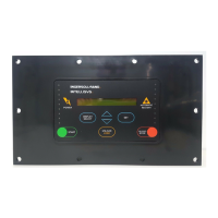
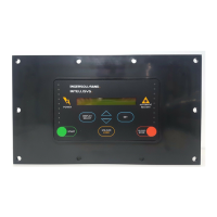
4.1 operator panel layout
4.1.1 sequencer start button
4.1.2 sequencer stop button
4.1.3 sequencer status button
4.1.4 compressor status/right
arrow button
4.1.5 set button
4.1.6 up and down arrow buttons
4.1.7 “power” led
4.1.8 “sequencer” led
4.1.9 compressor unit status led’s
4.1.10 “alarm” led
4.2 setting up the ISC
4.2.1 initialization
4.2.2 pressure set up and control
4.2.3 sequence set up
4.2.4 compressor control
4.2.5 sequence rotation modes
4.3 starting and stopping
4.4 ISC status
4.5 compressor status
4.6 alarms
5.0 TROUBLE SHOOTING CHART
6.0 REFERENCE DRAWINGS
6.1 ISC set point map
6.2 “compressor control” set points
6.3 “initial set up” set points
6.4 “pressure settings” set points
6.5 “pressure control” set points
6.6 “sequence set up” set points
6.7 “sequence rotation mode” set points
6.8 installing modular plug connector
6.9 modular plug connections
6.10 electrical schematic
6.11 general arrangement
6.12 typical ISC installation
6.13 typical air system
7.0 PARTS LIST
8.0 MAINTENANCE RECORDS
TABLE OF CONTENTS
2
 Loading...

