Installation manual
Control panel and peripherals 11
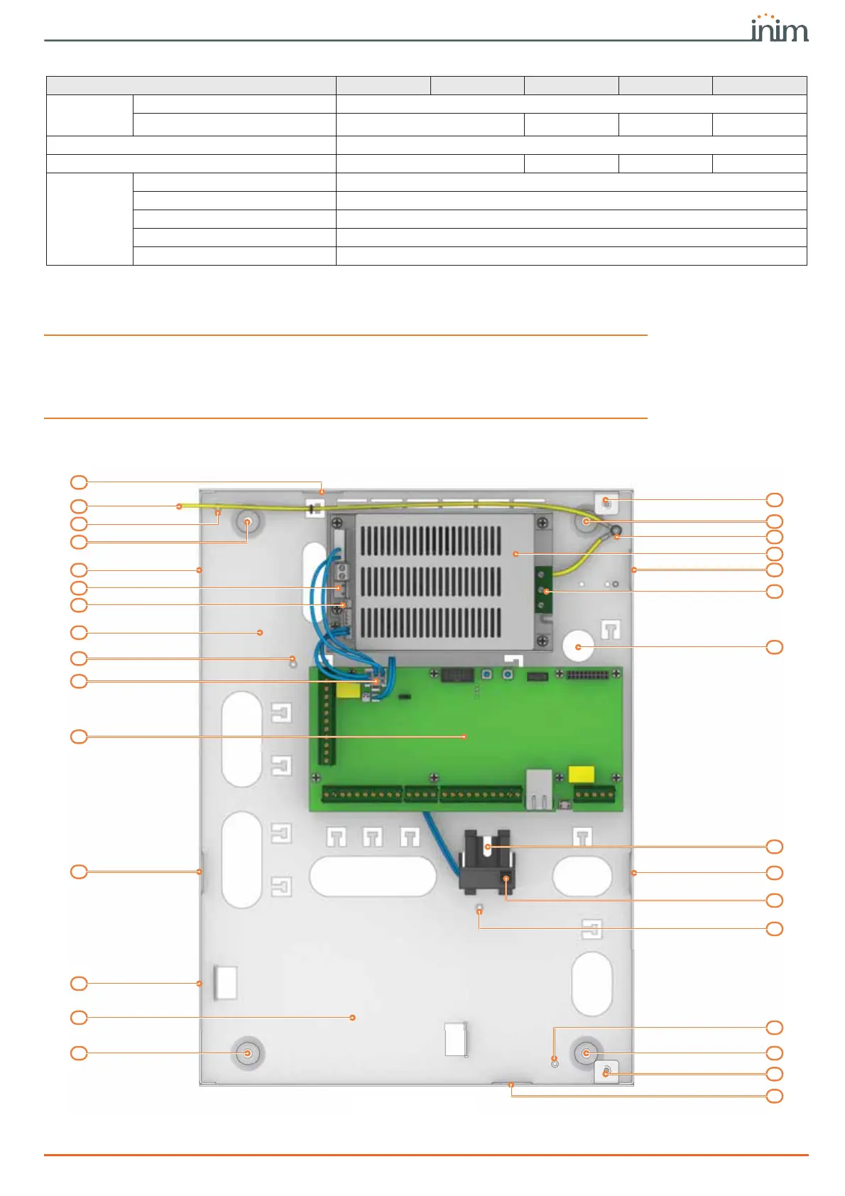
Following is an illustration of Prime control panels when open showing their assembled parts
and completed wiring, as supplied.
ATTENTION!
Do not tamper with or disconnect any wiring that has been completed at the factory.
In the event of the necessary replacement by the installer of one of the parts indicated below
(for maintenance or repairs), the manufacturer recommends that connection or
disconnection of any wires is done only after disconnecting both the AC mains voltage and the
battery.
terminals on
expansion
boards
total 500
available 60 120 240 500
Virtual terminals 15
Total terminals 60 120 240 500
Outputs on
control-panel
motherboard
total 15
terminals (T1, ..., T10) 10
relay 1
open collector (OC1, OC2) 2
Auxiliary outputs (AUX1, AUX2) 2
Table 2-4: Number of terminals
Prime control panel models Prime060S Prime060L Prime120L Prime240L Prime500L
M
N
M
H
C
R
R
K
K
N
F
N
P
G
O
N
I
M
A
B
N
K
Q
Q
J
K
M
E
D
L
Prime060S

 Loading...


