Installation manual
General description 15
EN12094-1:
To guarantee compliance of the product to EN 12094-1, the control panel must be configured to make
available the following functions (the others are optional):
Manual extinction, Electrovalve, Pre-extinction, Release.
The "Electrovalve" function must only be associated with the "I/O4" terminal on board the control panel.
The "Pre-Extinction" function at default is associated with the terminal "I/O3" on board the control panel.
Refer to the Configuration Manual for the programming details of the other functions.
EN12094-1:
In compliance with the requirements of standard EN 12094-1, if the “Stop extinction-Abort” function is
used in a Previdia Compact control panel, the “Stop Extinction-Hold” and “Stop Extinction-Add” functions
cannot be activated, and vice versa.
Please remember that no more than 32 devices can be connected to each of the selected input or
output terminals.
2.4 Previdia-C-DIAL, telephone line Communicator module
The optional Previdia-C-DIAL board allows you to connect Previdia Compact control panels to the landline (PSTN) and to
the GSM 2G and 3G networks.
It manages reporting protocols used by alarm receiving centres. This module allows the control panel to make voice
calls and send SMS text messages.
The board comes with:
• Mounting plate
•7 mounting screws
• cable for the connection to the motherboard
• remote antenna
• Instructions manual
SIM card not included
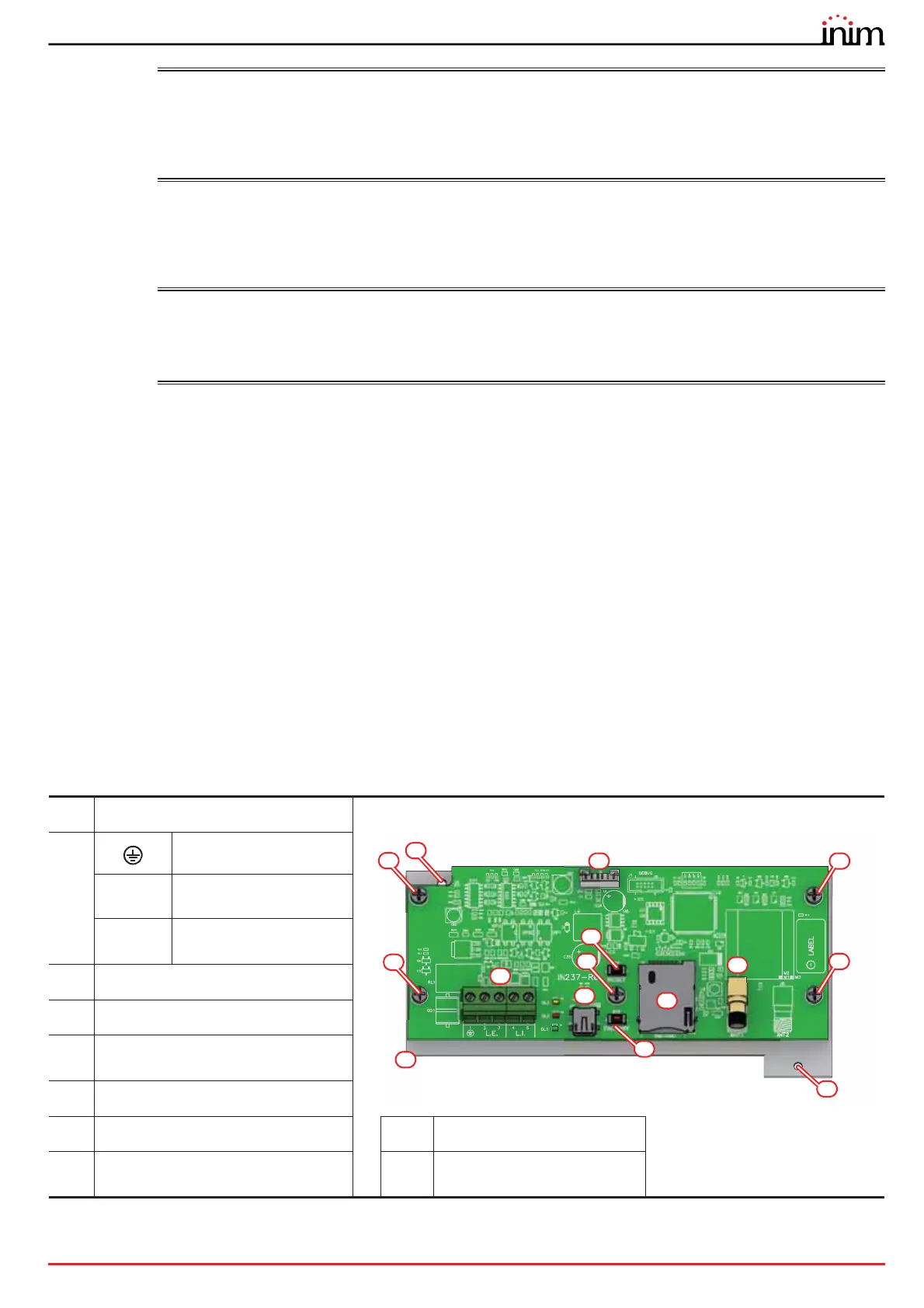
[A]
Motherboard connector
[B]
Ground terminal
L.E.
Telephone line
connection terminals
L.I.
Internal telephone line
terminals
[C]
Mini USB port
[D]
Reset button
[E]
Button to reset default settings
(factory settings)
[F]
SIM card holder
[G]
GSM antenna connector
[I]
Mounting plate
[H]
Screws for fixing the board to the
plate
[J]
Hole for the mounting plate
screw
A
C
B
F
G
D
H
H
J
H
J
H
H
I
E