12 General description
Fire detection and extinguishant system
2.3 Fire Extinction
Some models of Previdia Compact control panel allow the management of a gas-extinguishing channel.
Complies with EN12094-1 and provides the inputs, outputs and control logic required by these systems.
The following figure shows a flowchart of the operations carried out by the control panel in the pre-extinction phase,
that is, from the occurrence of the events that trigger the extinction phase to the start of the release condition, and
during the release of fire extinguishing gas:
9, 10
+ L1.O -
500mA Terminals of loop 1
Output
12, 13
+ L1.I -
Input
14, 15
+ L2.O -
500mA Terminals of loop 2
Output
17, 18
+ L2.I -
Input
11, 16 / Earth terminal
19, 20
+ I/O1 -
1A @ 27.6V
Input/Output connection terminals
21, 22
+ I/O2 -
1A @ 27.6V
23, 24
+ I/O3 -
1A @ 27.6V
25, 26
+ I/O4 -
1A @ 27.6V
27, 28, 29
NO, C, NC
5A @ 30V Free voltage relay
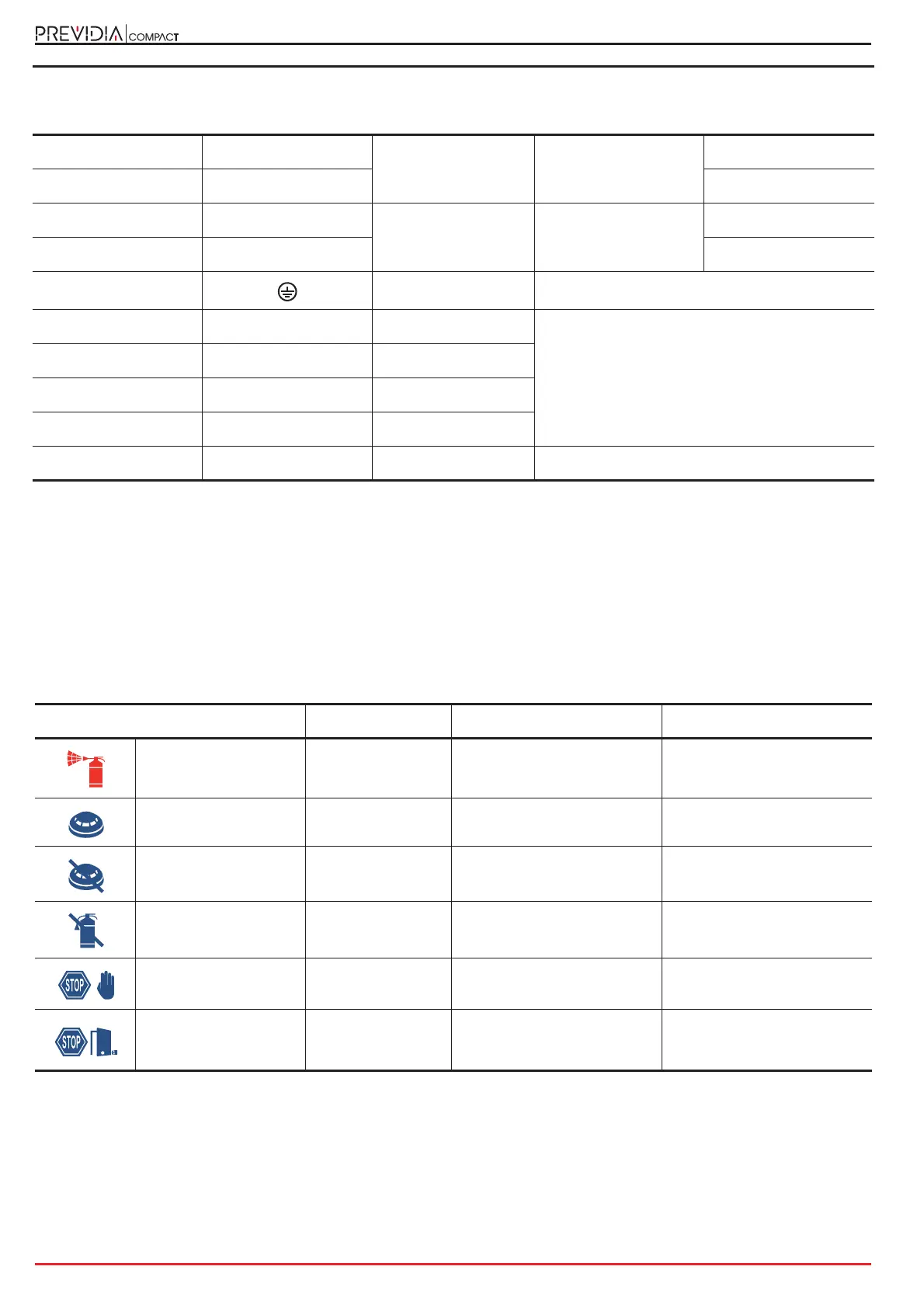
LED Colour On solid Flashing
Extinguishment
channel activation LED
Red Discharge activated
Pre-extinguishment condition
running
Automatic activation
indicator LED
Red
Automatic discharge
command activated
Automatic discharge
command partially activated
Bypass automatic
activation LED
Yellow
The automatic discharge
command has been bypassed
/
Bypass extinction
channel LED
Yellow Channel bypassed /
Manual stop extinction
LED
Yellow Extinguishment locked Fault on stop-extinction circuit
Stop extinction LED
from non-electrical-
devices
Yellow Extinguishment locked Fault on stop-extinction circuit
Output connection terminals
number name maximum current function