Installation manual
General description 17
The repeaters can be connected to the system via the Hornet+ network (paragraph 3.7 Connecting the Hornet+
network) or via a TCP-IP connection and can also be associated with Previdia Max control panels.
If necessary, it is possible to power the repeater using an external power supply module.
EN54:
The power-supply unit employed must be EN54-4 standard compliant.
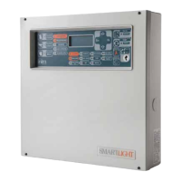
2.6 Control panels in a Hornet+ network
In order to enlarge the installation, it is possible to connect several Previdia Max
and Previdia Compact control panels (with a maximum of 48 points including
control panels and repeaters) thus creating an expanded system (Hornet+
network).
Each model of the Previdia Compact control panel provides two RS485 ports for
the ring connection (for details on the wiring refer to paragraph 3.7 Connecting
the Hornet+ network).
For further information regarding the method used for connecting control
panels in a network refer to the Previdia Networking Guide available at
www.inim.biz
2.7 Control Panels in an IP network
Several Previdia-Max and Previdia Compact control
panels or more Hornet+ control panel networks can be
connected to each other via a TCP-IP connection.
Each node in a connection of this type is identified as a
“cluster”. Each cluster can consist of a single control
panel, a Hornet+ network of control panels or a
repeater.
For further information regarding the method used for
connecting control panels in a network refer to the
Networking Guide available at www.inim.biz
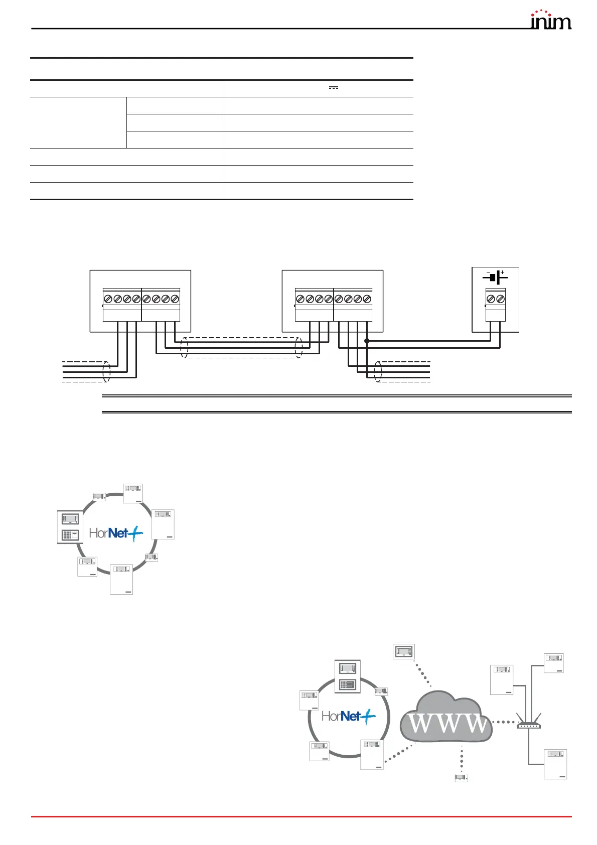
Technical specifications
Supply voltage 19-30 V
Consumption @
27.6V
stand-by 110mA
during mains failure 80mA
maximum 130mA
Operating temperature from -5°C to +40°C
Dimensions 210 x 132 x 32mm
Weight 330g
21 3
A+
-
A-
4
+24
65 7
B+
-
B-
8
+24
21 3
A+
-
A-
4
+24
65 7
B+
-
B-
8
+24
-
+
Previdia Compact
Repeater
Previdia Compact REP
24V
LAN
Router
Internet