26 Installation
Fire detection and extinguishant system
3.9 Wiring the external communicators
The Previdia Compact control panels can be used to drive remote alarm or fault signalling devices
Cables:
2-wire shielded cable
Proper section (minimum 0.5mm², maximum 2.5 mm²)
Compliant with local laws and regulations in force
The “I/O” terminals on-board the control panel [A] and the outputs supervised on the loop modules can be used to
create an E-type output (output for the activation of alarm signalling on a remote signalling device, as prescribed by
standard EN54-2).
To create a J type output (output for activation of fault status signalling on a remote signalling device, as prescribed by
standard EN54-2), only the “I/O” terminals can be used on board the control unit, which can be Programmed as active in
rest condition.
EN54:
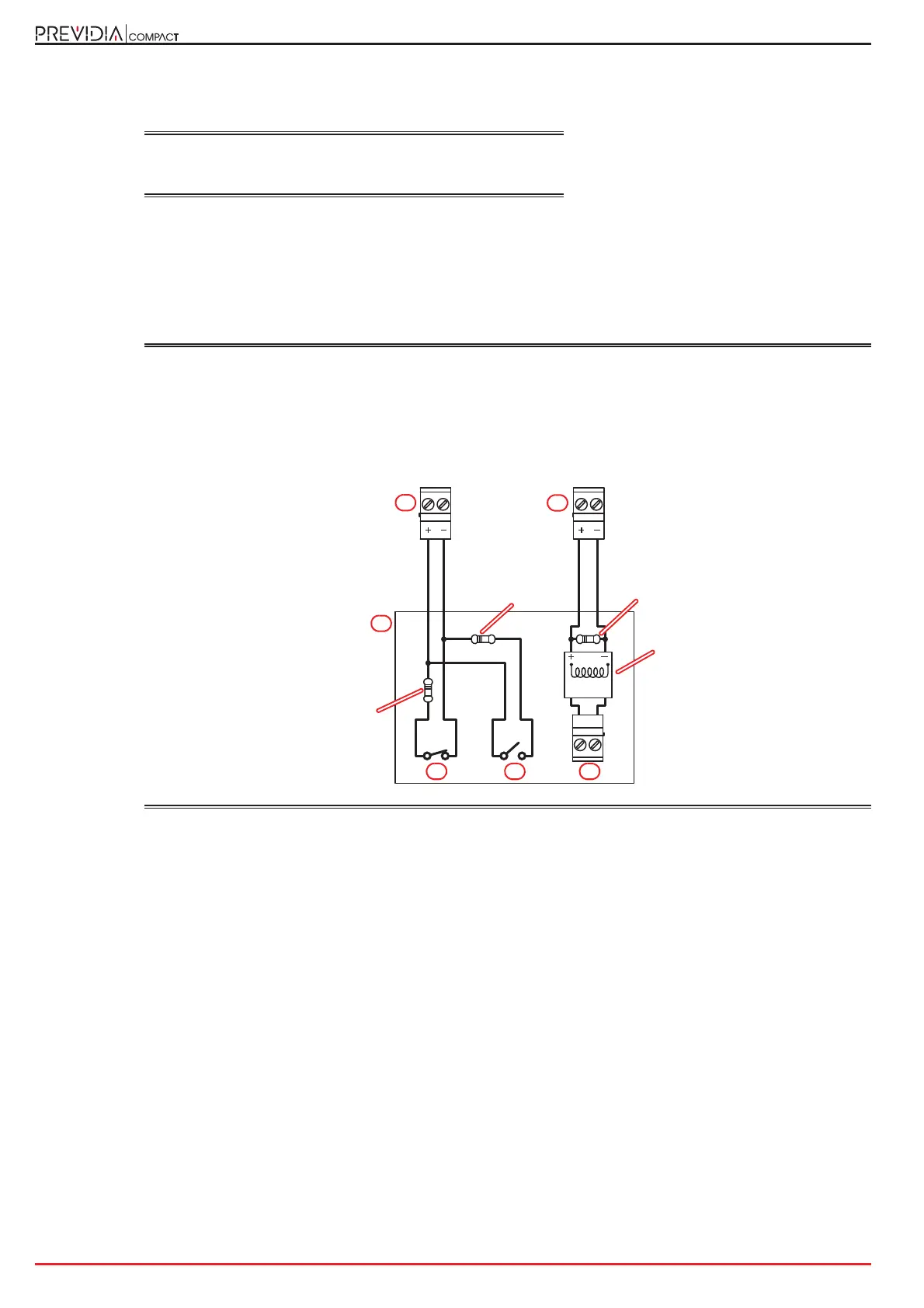
In both cases, as the external communicator, you must use a remote communication device compliant
with standard EN54-21 [B] and equipped with a supervised activation input [C], a normally closed fault
signal output [D] and a normally-open output for confirming successful communications [E]].
If the external Communicator does not have a supervised activation input, the connection to the control
panel can be carried out by means of a relay, which must be installed inside the communicator casing.
To transmit alarm events via the I/O terminals on board the control panel, you can use normal wiring for
non-polarized devices. To transmit failure events, use the following wiring diagram
:
I/Ox I/Ox
C
NONC
3K9Ohm
orange, white,
red
B
CE
D
A
470Ohm, 2W
yellow, purple,
brown
A
Relay 24V
470Ohm
yellow, purple,
brown